


Operator’s Manual LBA-PC
200
color or gray scale and displayed in the beam window.
FrameNumber=52;
CommentLine=This will appear in the title bar;
WriteProtect=1(^END)
10.6.3 PFS? - Pass/Fail Status
To retrieve the current pass/fail status, you must send the PFS? command.
The LBA-PC responds by repeating PFS followed by a “key=value” parameter for each value that has
pass/fail testing enabled. The ‘key’ is an ASCII text string identical to the label displayed in the left-
hand column of the results window. The ‘value’ is a boolean, where 0 equals fail and 1 equals pass.
The following example describes how the host controller retrieves the current pass/fail testing status.
Total, Peak, Centroid X, and Centroid Y are being tested. Total passed, Peak failed, Centroid X failed,
Centroid Y passed.
Host sends
:PFS?
LBA-PC sends
PFS
Total=1;
Peak=0;
Centroid X=0,
Centroid=1(^END)
10.7 COORDINATE SYSTEMS
10.7.1 Spatial Coordinates
The visible spatial coordinate system of the LBA-PC is called world coordinates. World coordinates are
used for computed centroid location and peak location, aperture location, cursor and crosshair
location, and pass/fail centroid and peak locations. World coordinates are defined by the Origin
Location, ‘Lens’ setting, and Pan Location. The world coordinates system is the only coordinate
system that is used when using the LBA-PC in the local, non-remote mode.
When operating the LBA-PC remotely, you must be aware of two other coordinate systems called
detector and frame coordinates. Detector coordinates are represented on the LBA-PC display by the
Pan/Zoom window. Detector coordinates are used to describe the active pixels of the camera
detector. Frame coordinates are used to describe the frame data stored in the frame buffer.
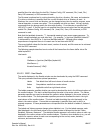
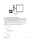
The figure below shows the relationship between the Pan/Zoom window, the capture window, frame
data, and the Beam display window. The Pan/Zoom window represents the active area of the camera
detector. The capture window, represented in the LBA-PC display by the dark gray square inside the
Pan/Zoom window, represents the location and size of the area of the detector that will be digitized.
The digitized data is placed in the frame buffer. Data in the frame buffer is then converted to false