


27104AF
18
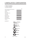
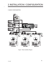
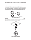
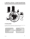
2.2 Connecting Wiring
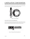
The dome camera can be controlled remotely by an externaI device or control system, such as control keyboard,
using RS-485 half duplex, RS-422 duplex or simplex serial communications signaIs. Connect marked RX+, RX- to
TX+ and TX- of the RS-485 control system.
A. CONNECTING RS-485/422
If control system is RS-422, connect TX+(TRX+), TX-(TRX-) of the dome camera to TX+, TX- and RX+, RX- of the
control device respectively.
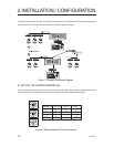
Connect the video out (BNC) connector to the monitor or video input.
B. CONNECTING VIDEO OUTPUT CONNECTOR
C. CONNECTING ALARMS
AL1 to 8 (Alarm In)
You can use externaI devices to signaI the dome camera to react to events. Mechanical or electrical switches can be
wired to the AL (Alarm In) and GND (Ground) connectors. See Chapter 3 - Program and Operation for Configuring
Alarm Input.
Note: All the connectors marked GND are common.
Connect the ground side of the alarm input and/or output to the GND connector.
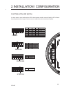
NC (NO) 1 TO 4 (NormaIly Closed or Normally Open: Alarm Out)
The dome camera can activate external devices such as buzzers or lights. Connect the device to the NC (NO)
(Alarm Out) and COM (Common) connectors. See Chapter 3 - Program and Operation for Configuring Alarm
Output.
Connect the AC 24V 850mA Power Adaptor to the OPTIX dome camera.
2. INSTALLATION / CONFIGURATION
D. CONNECTING THE POWER