


8(E)
Internal Swicth Settings
CA-570/570P
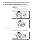
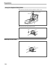
Unscrew the four screw
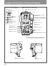
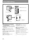
Internal Switch Settings
CA-570/570P
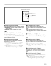
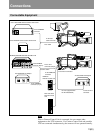
1 PROMPTER/GENLOCK switch
2 INTERCOM and GAIN switches
Unscrew the four screws.
MD TF AU AU
PROMPTER
INTERCOM
2
GAIN
CM
+
0
–
DYN
GENLOCK
INTERCOM
1
GAIN
CM
+
0
–
DYN
1 PROMPTER/GENLOCK (prompter signal
input and output/external sync signal input)
switch (MD-119 board)
Selects the PROMPT/GENLOCK connector function.
PROMPTER: Inputs and outputs a prompter signal
(factory setting).
GENLOCK: Inputs an external sync signal.
2 INTERCOM and GAIN switches (AU-237
board)
Set these switches to specify the type of microphone
connected to the INCOM 1 and INCOM 2 connectors
and their respective gain.
INTERCOM 1/2 switches
CM: carbon microphone (factory setting)
DYN: dynamic microphone
GAIN 1/2 switches
+: Raises the gain 6 dB above standard gain
0: Standard gain
–: Lowers the gain 6 dB below standard gain
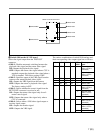
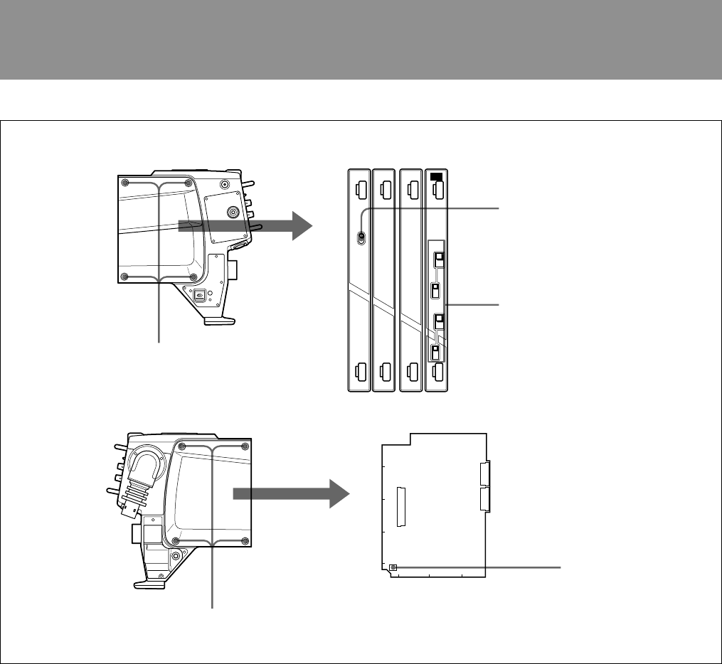
3 Switch S1 on the MB-783 board
Specifies the type of audio signal output from the
EARPHONE jack.
• S1-1: Set to ON to output the program audio signal.
• S1-2: Set to ON to output the audio signal of
intercom 1.
• S1-3: Set to ON to output the audio signal of
intercom 2.
• S1-4: Set to ON to output the VTR playback audio
signal.
All switches are factory set to OFF, except S1-1.
Switch on the MB-783 board
3 Switch S1
CN10
CN11
CN25
S1
1234
E
D
C
B
A