


10(E)
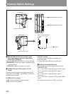
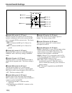
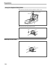
Internal Swicth Settings
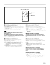
!§ Switch S351 on the AU-251 board
Set to ON to monitor the microphone input on a
headset. The factory setting is OFF.
!¶ Switch S700 on the AU-251 board
Turns the power supply (48 V) to the external
microphone on and off.
!• Switch S200 on the AU-251 board
• S200-1: When S200-1 is set to ON, the battery alarm
signal is mixed with the tally lamp signal. This
switch is factory set to OFF. In this position, the
indicator in the viewfinder is unaffected.
• S200-2: When a CCU is connected to the CA-570/
570P, this switch specifies whether power is supplied
from the REMOTE connector or not.
ON: When a CCU is connected, the power is
automatically turned off. When the camera is
used as a stand-alone unit, the power is turned on
(factory setting).
OFF: The power is supplied from the REMOTE
connector.
!¡ Switch S181 on the AU-237 board
When the dynamic microphone used for the incom
headset is unbalanced, this switch connects the MIC
pin Y to ground (GND) to prevent noise. The factory
setting is OFF.
S181-1: Connects the MIC pin Y of Incom 1 to
ground.
S181-2: Connects the MIC pin Y of Incom 2 to
ground.
!™ Switch S111 on the AU-237 board
Sets the INCOM 1 connector to either RTS mode or
NORMAL mode. The factory setting is NORMAL
mode.
!£ Switch S5 on the AU-237 board
When this switch is set to ON, the intercom audio is
mixed with the program audio. The factory setting is
OFF.
!¢ Switch S800 on the AU-251 board
Turns the power supply (12 V) to the external
microphone on and off. No power is supplied if the
MIC power switch on the rear panel is set to OFF or to
+48V. The factory setting is OFF.
!∞ Switch S600 on the AU-251 board
Specifies input of the audio input signal from the
MIC1 connector on the camcorder or the AUDIO IN 1
connector on the CA-570/570P.
C: Input from the MIC 1 connector on the
camcorder.
CA: Input from the AUDIO IN 1 connector on the
CA-570/570P.
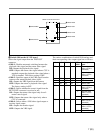
F
E
D
C
B
A
1234
CN1
E1
E111
E301
E451
RV111
RV112
RV301
RV302
RV411
S1
S2
S3
S4S5
S111
S181
S182
S183
S301
S302
S362
S363
S411
TP111
TP301
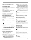
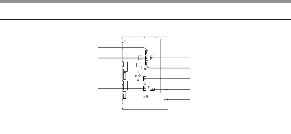
Switch on the AU-237 board
6 Switch S3
7 Switch S4
8 Switch S2
9 Switch S302
0 Switch S411
!¡ Switch S181
!™ Switch S111
!£ Switch S5