


7
Chapter 7 Location and Function of Parts and Controls 109HDC-900/950/930 Series Product Information Manual
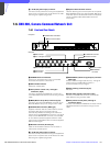
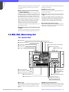
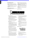
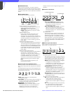
l PICTURE MONITOR buttons
Press to select the output signal from the PIX2
OUTPUT connector of CCU.
The signal corresponding to the lit button is output.
R/G/B: Select the R signal, G signal, or B signal. The
signals can be selected either independently or in
combination. When any of these buttons is pressed,
the ENC circuit is turned off.
ENC (encode): When this button is pressed, the R/G/
B circuits are turned off, and the ENC signal is
output.
m WAVEFORM MONITOR buttons
Press to select the output signal from the WF2 OUTPUT
connector of CCU.
The signal corresponding to the lit button is output.
R/G/B: Select the R signal, G signal, or B signal. The
signals can be selected either independently or in
combination. When any of these buttons is pressed,
the SEQ and ENC circuits are turned off.
SEQ (sequence): When this button is pressed, the R/
G/B circuits are turned off, and the SEQ signal is
output. You can monitor the waveforms of the three
R, G, and B signals in sequence on a waveform
monitor.
ENC (encode): When this button is pressed, the R/G/
B and SEQ circuits are turned off, and the ENC
signal is output.
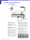
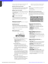
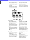
n Camera select block
A PANEL ACTIVE button
Press and light up this button to permit the
cameras selected with the camera select
buttons to be controlled from this unit. The IRIS/
MB ACTIVE button also lights up. If you press
the button when lit, it goes dark and the
operation panel of this unit is locked.
B PARA (parallel mode) button
Press and light up this button to activate Parallel
mode, which enables concurrent operation with
another control panel. If you press the button
when lit, it goes dark and Parallel mode is
canceled.
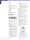
C MULTI indicators
Show the Master/Slave status of the
corresponding cameras 1 through 12 (when the
EXPAND button is not lit) or 13 through 24 (when
the EXPAND button is lit).
The indicator for the camera which is specified
as the master for Master/Slave mode lights in
green. The indicators for the slave cameras light
in orange. They light in red during the auto setup
of the corresponding cameras. If an error occurs
during the auto setup and the operation is
interrupted, they will flash in red.
D TALLY indicators
Show the tally status of the corresponding
cameras 1 through 12 (when the EXPAND
button is not lit) or 13 through 24 (when the
EXPAND button is lit). The corresponding
indicator lights in red when a red tally is sent to
a camera, and it lights in green when a green
tally is sent. When both red and green tally are
sent, it lights in orange. When a call signal is
sent to the camera, the indicator rapidly flashes
in red.
E Active indicators
Show the control status of the corresponding
cameras 1 through 12 (when the EXPAND
button is not lit) or 13 through 24 (when the
EXPAND button is lit). The indicators for the
cameras under control of this unit light in green
and the indicators for the cameras under control
of another control panel light in orange. An
indicator whose corresponding camera (or
camera control unit) is not connected does not
light. An indicator lights in red when an error is
detected and the self-diagnostic functions are
activated in the corresponding camera or
camera control unit.
F Camera select buttons
Select the cameras to be controlled from this
unit. Press and light up the button
corresponding to each desired camera.
Cameras 1 through 12 are selected when the
EXPAND button is not lit, and cameras 13
through 24 are selected when the EXPAND
button is lit.
G EXPAND button
Press to select the group to be selected with the
camera select buttons. Cameras 1 through 12
can be selected when this button is not lit, and
cameras 13 through 24 can be selected when
this button is lit.
Note
An appropriate camera command network unit
(CNU- 700, etc.) is required to control multiple
cameras using the camera select function.
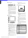
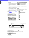
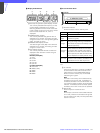
o Filter control block
A FILTER CTRL (filter control) button
Press and light up the button to enable filter
selection with the CC and ND filter select
buttons of this unit.
B ND (ND filter select) buttons
While the FILTER CTRL button is lit, press and
light up one of these buttons to select the
corresponding ND filter.
123456789101112
PARA
PANEL
ACTIVE
EXPAND
MULTI
TALLY
3
12
76
4
5
12345
ABCDE
ND
CC
FILTER CTRL
2
1
3