


7
Chapter 7 Location and Function of Parts and Controls 88HDC-900/950/930 Series Product Information Manual
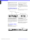
position turns the power on, and setting it to " " turns it
off. The indicator lights when the power supply is on.
g CAMERA POWER switch and indicator
Turns on or off the power to the camera when the MAIN
POWER switch is on. Setting the switch to the " I"
position turns the power on, and setting it to "O " turns
it off. When a remote control panel is connected and
the power supply is turned off with the CAM PW button
on the remote control panel, this switch alone cannot
turn on the video camera power.
h INTERCOM connector (XLR 5-pin)
Connects to a headset.
Note
To use a headset with a plug other than an XLR 5-pin
plug, consult a Sony service or sales representative.
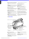
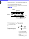
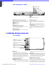
7-3-2 Rear Panel
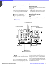
a CAMERA connector (optical fiber connector)
Used to connect a video camera, using an optical fiber
cable such as the FC2-PD50/PD250. All video camera
signals, including power supply, control, video, and
audio, are sent and received over one optical fiber
cable.
Note
Dust on the connection surface of the optical fiber
cable may result in transmission errors. When not
connected, always cover the end with the supplied
cap.
b AC IN (AC power supply input) connector
Use the supplied power cord to connect to an AC
power supply. The power cord may be secured to the
HDCU-900 body using the supplied plug holder.
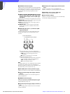
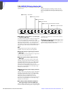
c Remote control connectors
A RCP/CNU REMOTE connector (8-pin)
Used to connect to an MSU-700A/750 Master
Setup Unit, CNU-500/700 Camera Command
Network Unit, or RCP-700 series Remote Control
Panel via a CCA-5 Connection Cable. Control
signals are sent and received via this connector.
When using an RCP-700 series unit, power is
also supplied.
B WF MODE REMOTE (waveform monitor remote)
connector (D-sub 15-pin)
Used to attach to the appropriate connector on
a waveform monitor when operating the
waveform monitor display using an MSU-700A/
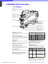
1 CAMERA connector
2 AC IN
connector
8 Expansion slot
3 Remote control connectors
4 CHARACTER OUTPUT connector
5 DIGITAL AUDIO connector
6 MIC OUTPUT connectors
7 INTERCOM/TALLY/PGM connector
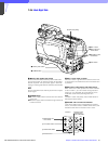
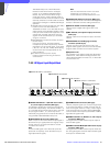
HD signal input/output block
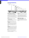
SD signal input/output block
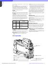
REMOTE
I/O PORT
TRUNK LINE
RCP/CNU
MIC
WF
1 RCP/CNU REMOTE connector
2 WF REMOTE connector
3 TRUNK LINE connector
4 MIC REMOTE connector
5 I/O PORT connector