


8
Chapter 8 Connectors and Cables 165HDC-900/950/930 Series Product Information Manual
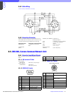
8-8. RCP-750/751, Remote Control Panel
8-8-1 Connector Input/Output Signals
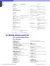
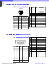
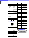
8-8-1-1 AUX REMOTE
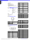
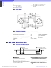
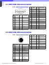
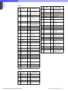
8-8-1-2 EXT I/O
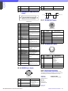
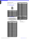
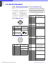
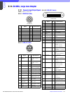
8-8-2 Connection Connector
Connections made with the connector panels during
installation or service should be made with the
connectors/complete cable assemblies specified in
the following list, or equivalent parts.
Connector function Connection connector
AUX REMOTE 1-706-848-11 PLUG, 8P MALE
or
CCU/CNU REMOTE Cable assembly (Option)
(8P, FEMALE) CCA-5-3 (3 m), CCA-5-10 (10
m),
CCA-5-30 (30 m)
EXT I/O 1-560-651-00 D-SUB 9P,
MALE
(9P, Female) 1-561-749-00 JUNCTION
SHELL 9P
No. Signal Specifications
1 TX (+) RCP SERIAL DATA
2TX (–)
3 RX (+) CCU/CNU/AUX
SERIAL DATA
4RX (–)
5 TX GND GND for TX
6 POWER (+) IN RCP POWER, +10 V to +30 V
7 POWER (–) IN GND for POWER
8SPARE
C CHASSIS GND CHASSIS GND
No. Signal Specifications
1 PREVIEW S1 CONTACT (X)
(Modification is required for
some units)
2 PREVIEW S2 CONTACT (Y)
(Modification is required for
some units)
3 SPARE I/O
PORT 1
(CMOS LEVEL 3.3 HI ACTIVE)
Assignable
4 SPARE I/O
PORT 2
(CMOS LEVEL 3.3 HI ACTIVE)
Assignable
5 SPARE I/O
PORT 3
(CMOS LEVEL 3.3 HI ACTIVE)
Assignable
6 SPARE I/O
PORT 4
(CMOS LEVEL 3.3 HI ACTIVE)
Assignable
7 SPARE I/O
PORT 5
(CMOS LEVEL 3.3 HI ACTIVE)
Assignable
8 POWER OUT +5V DC
9GND —
1
7
6
4
8
5
2
3
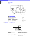
(External view)
CCU/CNU REMOTE
(8P, Female)
15
96
(
External view
)
(9P Female)