


7
Chapter 7 Location and Function of Parts and Controls 91HDC-900/950/930 Series Product Information Manual
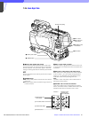
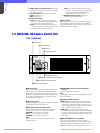
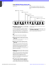
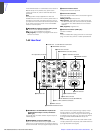
7-3-5 HKCU-901 SD Analog Interface Unit
The optional HKCU-901 is - installed in the HDCU-900
expansion slot.
Note
All input and output connectors function when the
system is operated at a 59.94/50 Hz field frequency,
but do not operate when the system field frequency is
60 Hz.
a RET INPUT 1-4 (return video 1, 2, 3, and 4 input)
connectors (BNC type)
Four different SD analog return video input signals may
be received independently. The selection of RET
1, 2, 3, or 4 is made by the camera’s return switch. The
type of input signal on RET 1, 2, 3, and 4 may be set
individually using switches on the AT board in the
HDCU-900, or using the MSU-700A/750 Master Setup
Unit. The aspect ratio may also be selected for SD
signals.
Note
If a signal asynchronous with the HDCU-900 is
supplied, the picture quality may be degraded.
b SYNC OUT (SD sync signal output) connector
(BNC type)
Used for output of an SD composite sync signal from
the internal sync signal generator.
c PIX OUT (picture monitor output) connector
(BNC type)
Used for output of the picture monitor video signal
selected using the RCP-700 series Remote Control
Panel MONITOR SELECT button, or the MSU-700A/
750 Master Setup Unit PICTURE MONITOR button.
(When both the RCP and MSU are in use, this
connector can be assigned to the output connector for
MSU control.) Signal selection can be made using
switches on the AT board.
d WF OUT (waveform monitor output) connector
(BNC type)
Used for output of the waveform monitor video signal
selected using the RCP-700 series Remote Control
Panel MONITOR SELECT button, or the MSU-700A/
750 Master Setup Unit WF MONITOR button.
(When both the RCP and MSU are in use, this
connector can be assigned to the output connector for
MSU control.) Signal selection can be made using
switches on the AT board.
e Y/G, B-Y/B, and R-Y/R OUTPUT (component
video signal output) connectors (BNC type)
Used for output of either Y, B-Y, R-Y component video
or G, B, R component video signals. The type of signal
is selected using switches on the AT board. (Factory
setting: G, B, R)
f VBS OUT 1 and 2 (composite video output 1 and
2) connectors (BNC type)
The two connectors are for output of the video camera
signal in analog composite video format.
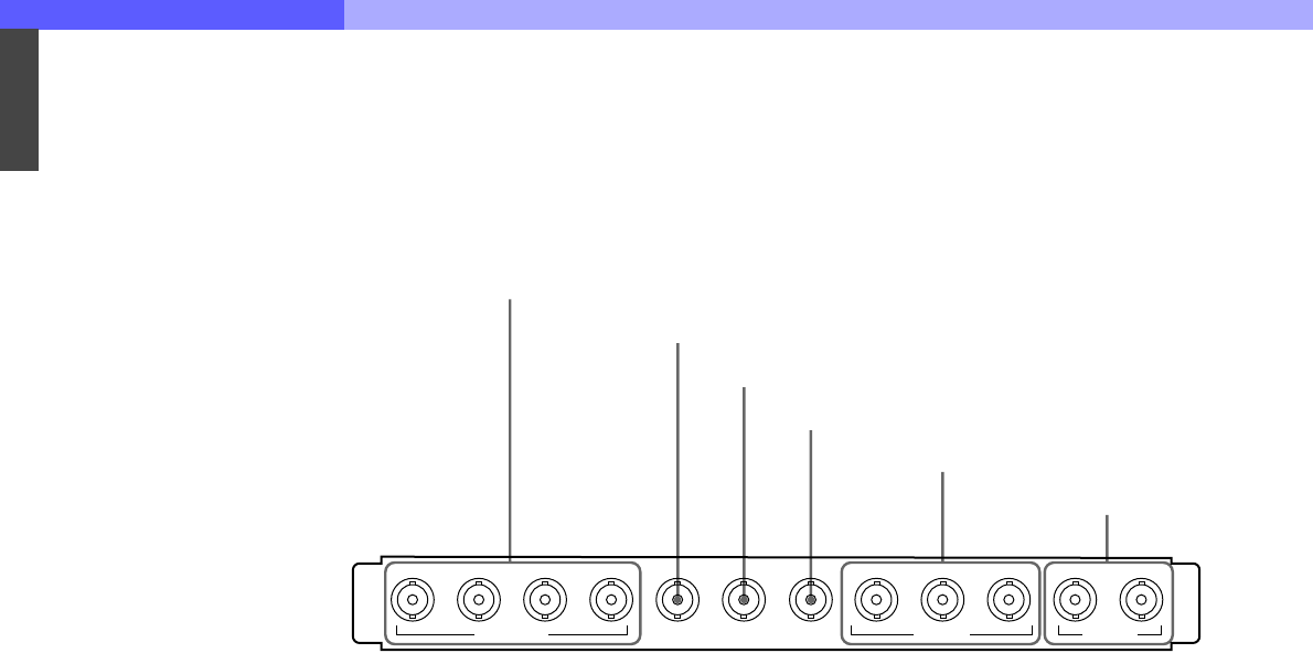
1234
PIX OUTSYNC OUT
OUTPUT
12
R-Y/RY/G B-Y/B
WF OUT
RET INPUT
VBS OUT
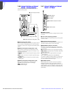
1 RET INPUT 1-4 connectors
2 SYNC OUT connector
3 PIX OUT connector
4 WF OUT connector
5 Y/G, B-Y/B, and R-Y/R OUTPUT connectors
6 VBS OUT 1 and 2 connectors