


8
Chapter 8 Connectors and Cables 161HDC-900/950/930 Series Product Information Manual
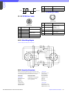
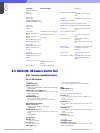
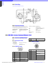
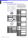
8-4-2 Cable Wiring
CCA-5 Cable (for REMOTE connector)
8-4-3 Connection Connector
Use the connectors below or the equivalent at its tip
when cables are connected to each connector on the
connector panel during installation and servicing.
Connector name Connectoin connector/cable
REFERENCE 1-569-370-12 Connector,
BNC
CHARACTER
(BNC)
RS232C (9P, FEMALE) 1-566-354-11
D-SUB, 9P MALE
CCU 1-766-848-11 PLUG, 8P MALE
RCP or CCA cable assembly
(option)
MSU CCA-5-10 (10 m)
VCS CCA-5-3 (3 m)
AUX 1/2/3/4 (8P,
FEMALE) CCA-5-30 (30 m)
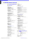
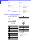
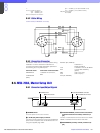
8-5. CNU-500, Camera Command Network Unit
8-5-1 Connector Input/Output Signals
Main connector input and output signals are shown
below.
8-5-1-1 BNC connector 75 Ohms
[Input Signal]
REFERENCE 300 mVp-p, loop through
[Output Signal]
CHARACTER 700 mVp-p,
300 mVp-p (SYNC)
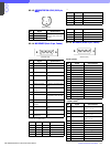
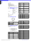
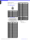
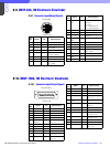
8-5-1-2 RS232C (9P, Female)
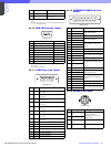
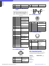
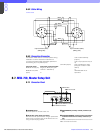
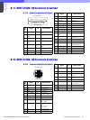
8-5-1-3 REMOTE (8P, Female)
Black
White
White
Brown
White
Red
Red
Brown
Brown
Orange
1
2
3
4
8
5
6
7
1
2
3
4
8
5
6
7
No. Signal Specifications
1 DCD IN DATA CARRIER DETECT
2 RXD (+) IN RECEIVED DATA
3 TXD (+) OUT TRANSMITTED DATA
4 DTR OUT DATA TERMINAL READY
5 SIGNAL GND SIGNAL GND
6 DSR IN DATA SET READY
7 RTS OUT REQUEST TO SEND
8 CTS OUT CLEAR TO SEND
5
9
6
1
(External view)
9NC —
No. Signal Specifications
1 TX (+) CNU SERIAL DATA
2TX (–)
3 RX (+) MSU/RCP/CCU/VCS/AUX
SERIAL DATA
4RX (–)
5 TX GND GND for TX
6 POWER (+)
*1
7 POWER (–)
*1
8SPARE
CHASSIS GND CHASSIS GND
No. Signal Specifications
1
2
3
4
5
6
7
8
(External view)
RCP/CCU/MSU/VCS/AUX