


4
Chapter 4 Control System 51HDC-900/950/930 Series Product Information Manual
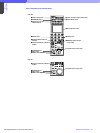
4-3. Camera Command Network Units – CNU-700 and CNU-500
The CNU-700 and CNU-500 Camera Command
Network Units are designed as the technical 'nerve
center' of a Star Shape Network System where all
commands such as 'All', 'Control Priority', 'Parallel/
Mode', etc. are centralized and distributed to the
respective HDCUs of the studio system. They are
furnished with an RS-232C port to provide interface
capability to external systems such as ISR (Interactive
Status Reporting), external PC or modem and robotics
control systems. They can be mounted in a 19-inch
standard rack (3U height for the CNU-700, and 1U
height for the CNU-500). Through the modem or PC,
camera data files can be transferred from a master
camera in a studio to cameras at several remote sites
during a live broadcast.
By employing a RISC-based microprocessor in the
CNU-700 and CNU-500, the communication speed
has been greatly improved. Consequently, real-time
control and instant response to the MSU-700A/750 or
RCP-700 Series commands have been made possible.
With the combination of one VCS-700 Video Selector
with a CNU-700 or CNU-500, each of six pictures and
six waveform monitoring video signals can be handled
(and expanded to 96 of each with eight CNU-700
units).
Through a CNU-700 or CNU-500, one RCP can
control one HDCU while one MSU is able to control
multiple HDCUs. All units connected to the CNU can
easily communicate with each other. Because of this
useful new -function, simultaneous control of multi
cameras, file transfer between multi cameras and
control from an external device are now possible.
As a convenient tool for system set-up and
maintenance, both MSU control routing and CNU
control assignment can be displayed on a monitor.
Since the CNU is the nerve center of a system, it has
a bypass facility to maintain communication between
the HDCUs and RCPs in the event of a CNU
malfunction or power loss. Therefore, even when the
power unit or AT board of the CNU-700 or CNU-500
has failed, camera heads and HDCUs can be directly
controlled from the RCPs to let program production
continue.
As mentioned in Section 2, Total System, the cost
versus performance balance between the two types of
Camera Command Network Units allows users to build
up systems that meet their application needs. The
CNU-500 is suitable for applications with up to six
cameras, while the CNU-700 can be expanded to
handle up to 12 cameras with use of the BKP-7930
optional expansion board.
(1) High-speed data transmission rates
CNU to MSU/RCP/HDCU: More than 500 Kbps
Camera Head to HDCU: 35 Kbps
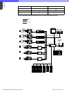
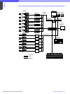
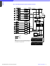
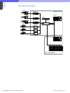
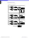
(2) System configuration
Basic system: Up to six cameras with one CNU-700
or CNU-500
Expanded system: Up to 12 cameras with one CNU-
700 with one BKP-7930 optional board installed
Maximum system: Up to 96 cameras with eight CNU-
700 units (each with a BKP-7930 optional board
installed) via I/O port on the rear panel (four MSU-
700A/750 Master Set-up Units required).
(3) Character display
Information concerning the camera heads and HDCUs
connected to the CNU-700 and CNU-500 can be
displayed on a monitor via the CHARACTER
connector. This includes:
• Camera settings
• System connection information
• Results of Auto set-up
• Self-diagnostics information
(4) Emergency feature
In the event of a problem with the CNU-700 and CNU-
500, turning their internal OPERATION switch to the
EMERGENCY position allows control signals from the
remote control panel to be directly connected to the
camera head. In this way, program production
cancontinue by bypassing the CNU.
Table 4-1:A comparison between the CNU-700 and CNU-500
CNU-700 CNU-500
Number of Cameras
connectable
Up to 6 cameras Up to 6 cameras
Up to 12 cameras with BKP-7930 fitted No
Up to 96 cameras with multi CNU
connected
No
Number of RCPs connectable
Up to 6 RCPs Up to 6 RCPs
Up to 12 RCPs with BKP-7930 fitted No
Up to 96 RCPs with multi CNU
connected
No
Multi MSU connectable Yes No
Multi VCS connectable Yes No
Other controller connectable Yes Available with optional AUX connector
Programable with remote
control
Yes No
RS-232C connector for ISR Yes Yes
RS-232C connector for
switcher etc.
One No
Two when BKP-7930 fitted No
REF. video in Yes Yes
Character out 2 1
Assignment between RCP and
CHU/CCU
Free Fixed