


– 14 –
ICX274AQ
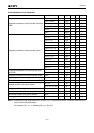
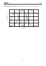
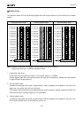
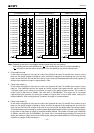
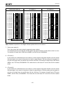
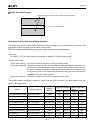
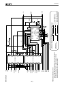
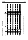
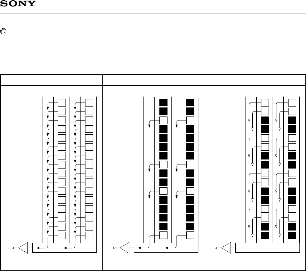
Note) Blacked out portions in the diagram indicate pixels which are not read out.
Output starts from line 1 in 2/8-line decimation mode.
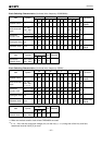
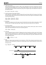
1. Progressive scan mode
In this mode, all pixel signals are output in non-interlace format in 1/14.985s.
All pixel signals within the same exposure period are read out simultaneously, making this mode suitable
for high resolution image capturing.
2. 2/8-line readout mode
All effective area signals are output in approximately 1/30s by reading out the signals for only two out of
eight lines (1st and 6th lines, 9th and 14th lines).
This readout mode emphasizes processing speed over vertical resolution, making it suitable for AE/AF and
other control and for checking images on LCD viewfinders.
3. 2/4-line readout mode
All effective area signals are output in approximately 1/20s by reading out the signals for only two out of
four lines (3rd and 4th lines, 7th and 8th lines, and so on).
Readout modes
The diagrams below and on the following pages show the output methods for the following nine readout
modes.
2/4-line readout modeProgressive scan mode 2/8-line readout mode
16 (V2C/V3C)
15 (V2C/V3C)
14 (V2A/V3A)
13 (V2B/V3B)
12 (V2C/V3C)
11 (V2C/V3C)
10 (V2B/V3B)
9 (V2A/V3A)
8 (V2C/V3C)
7 (V2C/V3C)
6 (V2A/V3A)
5 (V2B/V3B)
4 (V2C/V3C)
3 (V2C/V3C)
2 (V2B/V3B)
1 (V2A/V3A)
V
OUT
G
R
G
R
G
R
G
R
G
R
G
R
G
R
R
G
B
G
B
G
B
G
B
G
B
G
B
G
B
G
G
B
16 (V2C/V3C)
15 (V2C/V3C)
14 (V2A/V3A)
13 (V2B/V3B)
12 (V2C/V3C)
11 (V2C/V3C)
10 (V2B/V3B)
9 (V2A/V3A)
8 (V2C/V3C)
7 (V2C/V3C)
6 (V2A/V3A)
5 (V2B/V3B)
4 (V2C/V3C)
3 (V2C/V3C)
2 (V2B/V3B)
1 (V2A/V3A)
V
OUT
G
R
G
R
G
R
G
R
G
R
G
R
G
R
R
G
B
G
B
G
B
G
B
G
B
G
B
G
B
G
G
B
16 (V2C/V3C)
15 (V2C/V3C)
14 (V2A/V3A)
13 (V2B/V3B)
12 (V2C/V3C)
11 (V2C/V3C)
10 (V2B/V3B)
9 (V2A/V3A)
8 (V2C/V3C)
7 (V2C/V3C)
6 (V2A/V3A)
5 (V2B/V3B)
4 (V2C/V3C)
3 (V2C/V3C)
2 (V2B/V3B)
1 (V2A/V3A)
V
OUT
G
R
G
R
G
R
G
R
G
R
G
R
G
R
R
G
B
G
B
G
B
G
B
G
B
G
B
G
B
G
G
B