


360014937
Copyright ©2000 Toshiba corporation. All rights reserved.
- 602 -
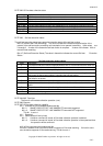
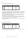
structure; the second error, the second error log structure; etc. The sixth error shall create an error log data
structure that replaces the first error log data structure; the seventh error replaces the second error log structure,
etc. The error log pointer indicates the most recent error log structure. If fewer than five errors have occurred, the
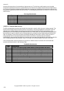
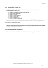
unused error log structure entries shall be zero filled. The following table describes the content of a valid error log
data structure.
Error log data structure
Byte Descriptions
n –n+11 First command data structure
n+12 –n+23 Second command data structure
n+24 –n+35 Third command data structure
n+36 – n+47 Fourth command data structure
n+48 – n+59 Fifth command data structure
n+60 – n+89 Error data structure
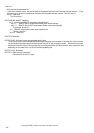
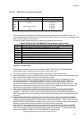
10.8.33.6.4 Command data structure
The fifth command data structure shall contain the command or reset for which the error is being reported. The
fourth command data structure should contain the command or reset that preceded the command or reset for
which the error is being reported, the third command data structure should contain the command or reset
preceding the one in the fourth command data structure, etc. If fewer than four commands and resets preceded
the command or reset for which the error is being reported, the unused command data structures shall be zero
filled, for example, if only three commands and resets preceded the command or reset for which the error is
being reported, the first command data structure shall be zero filled. In some devices, the hardware
implementation may preclude the device from reporting the commands that preceded the command for which the
error is being reported or that preceded a reset. In this case, the command data structures are zero filled.
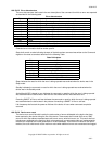
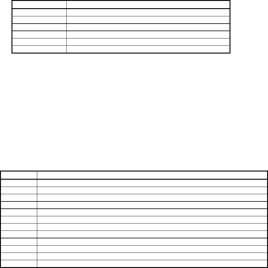
If the command data structure represents a command or software reset, the content of the command data
structure shall be as shown in the following Table.
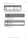
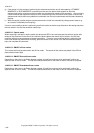
Command data structure
Byte Descriptions
n Content of the Device Control register when the Command register was written.
n+1 Content of the Features register when the Command register was written.
n+2 Content of the Sector Count register when the Command register was written.
n+3 Content of the Sector Number register when the Command register was written.
n+4 Content of the Cylinder Low register when the Command register was written.
n+5 Content of the Cylinder High register when the Command register was written.
n+6 Content of the Device/Head register when the Command register was written.
n+7 Content written to the Command register.
n+8 Timestamp
n+9 Timestamp
n+10 Timestamp
n+11 Timestamp