


360014937
Copyright © 2000 Toshiba corporation. All rights reserved.
-
533 -
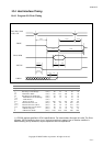
10.4 Host Interface Timing
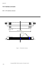
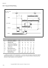
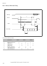
10.4.1 Program I/O Write Timing
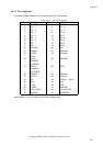
Transfer mode
Symbol Meaning 0 1 2 3 4
t
ASW
Address Setup to -DOW Low (min.) 70 50 30 30 25
t
DS
Data Setup to -DOW High (min.) 60 45 30 30 20
t
WE
-DOW Pulse Width (min.) 165 125 100 80 70
t
DH
Data Hold from -DOW High (min.) 30 20 15 10 10
t
AHW
ADDR Hold from -DOW High (min.) 20 15 10 10 10
t
WER
-DOW Inactive (min.) - - - 70 25
t
WCY
Write Cycle Time (min.) 600 383 240 180 120
t
CICSV
-IOCS16 valid from -CS (max.) 90 50 40 n/a* n/a*
t
AICSV
-IOCS16 valid from address (max.) 90 50 40 n/a* n/a*
t
AICSI
-IOCS16 inactive from address (max.) 60 45 30 n/a* n/a*
t
A
IORDY Setup time (max.) 35 35 35 35 35
t
B
IORDY Pulse Width (max.) 1250 1250 1250 1250 1250
(
*
) -IOCS16 shall be specified in ATA-2 specifications. For other modes, this signal is invalid. The Drive
releases -IOCS16 within the time of t
AICSI
, but how much time it takes to turn to inactive condition is
determined by pull up resistance, output impedance and line capacitance.
t
ASW
t
AHW
t
AICSI
t
A
t
B
t
AICSV
t
CICSV
t
DS
t
DH
t
WCY
t
WER
t
WE
DA2, DA1, DA0
-CS0, -CS1
-DIOW
DD15∼DD0
-IOCS16
IORDY