


360014937
Copyright ©2000 Toshiba corporation. All rights reserved.
- 552 -
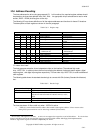
10.7.2.2 Diagnostic Mode
The drive enters diagnostic mode immediately after the power -on or after an Execute Diagnostics command.
Error bit in Status Register shall not be set in these cases. The following table shows bit values for the
diagnostic mode.
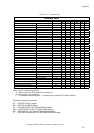
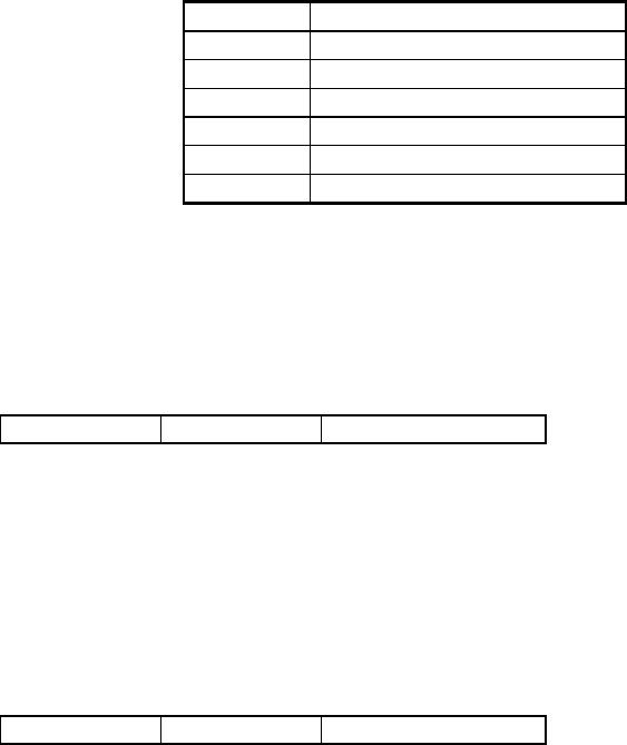
Table 10.7-1 Diagnostic mode error register
01 No errors
02 Controller register error
03 Buffer RAM error
04 ECC device error
05 CPU ROM/RAM error
06-7F reserved
8x Slave drive error (see below)
When two drives are daisy-chained on the interface, the MASTER drive has valid error information for
diagnostic mode. When the SLAVE drive detects an error, 80H and OR value (01 04) diagnosed by the
MASTER are set to the code above mentioned.
10.7.3 Features Register (Write Precompensation Register)
- CS0 DA2-DA0 : 1 Write only
Write precompensation is automatically optimized by the drive internally. This register is used with Set
Features command.
10.7.3.1 Smart command
This command is used with the Smart commands to select subcommands.
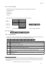
10.7.4 Sector Count Register
- CS0 DA2-DA0 : 2 Read / Write
10.7.4.1 Disk Access command
The sector count register determines the number of sectors to be read or written for Read, Write, and Verify
commands. A 0 in the sector count register specifies a 256 sector transfer. After normal completion of a
command, the content shall be 0.
During a multi-sector operation, the sector count is decremented and the sector number is incremented. If
an error should occur during multi-sector operation, this command shows the number of remaining sectors in
order to avoid duplicated transfer.
10.7.4.2 Initialize Device Parameters command
This register determines number of sectors per track.
10.7.4.3 Power Control command
This register returns a value in accordance with the operation mode (idle mode or stand-by mode).
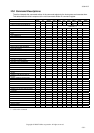
10.7.4.4 Set Features Command
If features register for this command is 03h, this register sets the data transfer mode.