


360014937
Copyright ©2000 Toshiba corporation. All rights reserved.
- 518 -
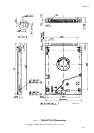
7.4.1 Screwing
Four screws should be tightened equally with 0.3 N
.
m ( 3 kgf
.
cm ) torque. The depth should be 3.0 mm
min. and 3.5 mm maximum.
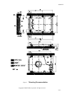
7.4.2 Installation
The drive should be mounted carefully on the surface of 0.1mm or less flatness to avoid excessive
distortion.
In order to prevent short-circuit under any circumstances, the space of 0.5mm or more should be kept under
the PCB and the design have to be checked carefully (See fig. 2).
Enough space should be kept around the drive especially around the convex portion of HDA (See fig. 2) to
avoid any contact with other parts, which may be caused by receiving shock or vibration.
The temperature of the top cover and the base must always be kept under 60 to maintain the required
reliability. ( If the drive runs continuously or spins-up frequently, the temperature of the top cover may rise to
15 maximum. If the drive is used in ambient temperature of 45 or more, it should be kept where
adequate ventilation is available to keep the temperature of top cover under 60 )
M3 mounting screw holes are tapped directly on the base for electrical grounding between the drive and the
base. In order to prevent the drive performance from being affected by the system noise, appropriate
evaluation should be conducted before deciding loading method.
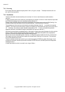
Be sure not to cover the breathing hole ( See fig. 1) to keep the pressure inside the drive at a certain level.
Don’t apply any force to the top cover except to the screw areas ( See fig. 2) on top cover. The maximum
force to the specified area is 2N.
The drive contains several parts which may be easily damaged by ESD(Electric Static Discharge). Avoid
touching the interface connector pins and the surface of PCB. Be sure to use ESD proof wrist strap when
handling the drive.
A rattle heard when the drive is moved is not a sign of failure.