


360014937
Copyright ©2000 Toshiba corporation. All rights reserved.
- 532 -
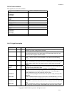
CSEL O 28 This pin and J2 (see 10.7) are used to determine the drive address, Master or
Slave. When J2 is ground, the drive works as a Master and when J2 is open, the
drive works as a Slave. If CSEL is negated then the drive runs as master drive If
CSEL is asserted then the drive runs as slave drive.
- DMACK O 29 Responding to DMARQ, this signal indicates that the host is ready to receive or
send the data.
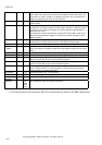
INTRQ I 31 Interrupt to the host system, enabled only when the drive is selected and the host
activates the - IEN bit in the Device Control register. When the - IEN bit is inactive
or the drive is not selected, this output is in a high impedance state, whether an
interrupt is set or not.
The interrupt is set when the IRQ bit is set by the drive CPU. IRQ is reset to zero
when host reads the Status register or a write to the command register or when
DRQ is negated.
- IOCS16 I 32 Indication to the host system that the 16 bit data register has been addressed and
that the drive is ready to send or receive a 16 bit data word (open drain).
DA 1 O 33 Address line from the host system to select the registers of the drive.
- PDIAG
CBLID
I/O 34 In Master/Slave mode, this signal reports the presence of slave drive to master
drive and enables transmitting of diagnostic result between master drive and slave
drive
DA 0 O 35 Address line from the host system to select the registers of the drive.
DA 2 O 36 Address line from the host system to select the registers of the drive.
- CS0 O 37 Chip select signal generated from the host address bus. This signal is used to
select one of the two groups of host accessible registers.
- CS1 O 38 Chip select signal generated from the host address bus. This signal is used to
select one of the two groups of host accessible registers.
- DASP I 39 This is a signal from the drive used either to drive an external LED whenever the
drive is being accessed, or to report presence of the slave drive to the master
when the drive is in master/slave mode.
RESERVED 27,44 Reserved for future use. No connection.
+ 5V (LOGIC) 41 Power line for logic and analog circuit.
+ 5V
(MOTOR)
42 Power line for driving motor.
GROUND 2,19
22,24
26,30
40,43
Ground between the drive and the host system.
(*1) ‘
I’
is from the drive to the host system, ‘
O
’ is from the host system to the drive, and ‘
I/O’
is bi-directional.