


VIVOTEK - A Leading Provider of Multimedia Communication Solutions
User's Manual - 5
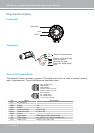
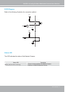
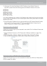
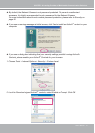
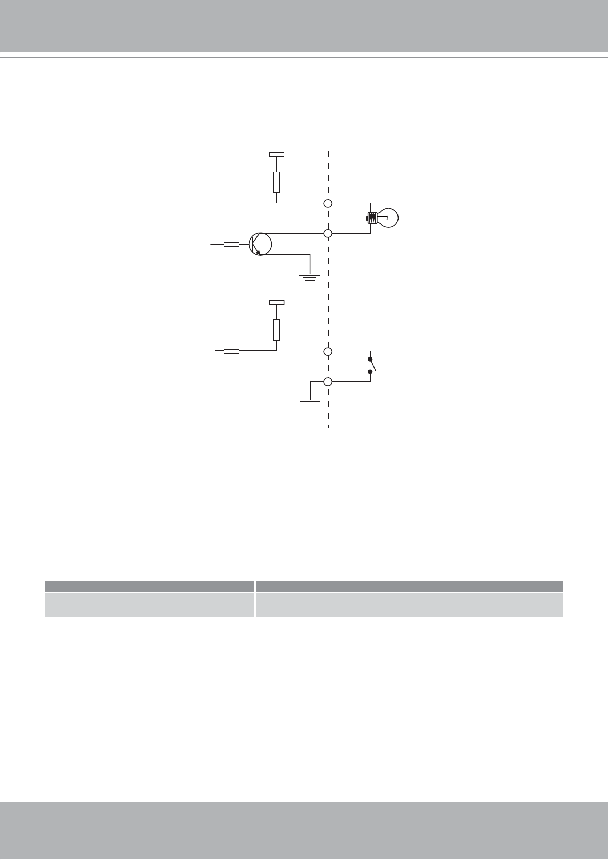
DI/DO Diagram
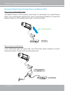
Refer to the following illustration for connection method.
12V
+12V
Digital output
PIN 1
Power+12V
PIN 2
Digital input
PIN 3
Ground
PIN 4
Status LED
The LED indicates the status of the Network Camera.
Status LED Description
Blinking red (two short, one long)
1. Power is being supplied to the Network Camera
2. Restore, or reboot the Network Camera