


AXIS 230 Unit Connections
49
Appendix D - Unit Connections
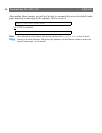
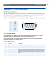
The D-Sub Connector
The AXIS 230 provides one 9-pin D-sub connector, providing the physical interface for an
RS-232 port, used for connecting accessory equipment; such as stand-alone Pan/Tilt
devices for the remote positioning of connected video cameras.
A diagram of the RS-232 connector, complete with pin assignment table, is shown below.
The Terminal Block
The terminal block is located on the rear panel and provides the interface to a single
transistor output, two digital inputs, an RS-485 interface and GND.
This section describes the pinout, interface support and the control and monitoring
functions provided by the terminal block.
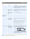
Terminal Block Pinout
Pin Function
1 CD
2 - RXD
3 - TXD
4 DTR
5 GND
6 DSR
7 RTS
8 CTS
9 RI
Pin Function Description
1 GND
2 Digital Input 1 1k internal pull-up. Connect to GND to activate.
3 Digital Input 2 1k internal pull-up. Connect to GND to activate.
4 Digital output Maximum current sink of 100mA (via logical 0 output.) Handles a maximum voltage of
24V DC, which is grounded at a maximum of 100mA. This output has an open-collec-
tor NPN transistor with the emitter connected to pin 1. If used with an external relay,
a diode must be connected in parallel with the load, for protection against voltage
transients.
5 RS-485-A (non-inverting) A half-duplex RS-485/422 interface for controlling auxiliary equipment.
6 RS-485-A (inverting)
54321
6789