


Unit Connections AXIS 230
52
Controlling and Monitoring
By entering http requests in your browser’s URL field, you can:
• drive the transistor output high or low
• monitor the status of the digital inputs
This requires administrator access to the AXIS 230, and thus a user name and password.
Log in as root and supply the root password (default = pass).
Tip!
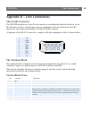
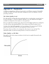
Transistor Output
The output can directly drive a maximum load of 24V DC at 100mA. By connecting
additional relay circuitry, heavier loads can be driven.
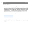
The transistor output is controlled using HTTP requests, as shown in the following
examples:
Example 1: - Set output 1 ON
Example 2: - Set two 300ms pulses with 500ms delay between the pulses, on output 1.
Example 3: - Wait 1 second before setting output 1 ON.
Digital Inputs
Two digital inputs allow the AXIS 230 to be configured for device triggered events. For
example, by connecting a motion detector to a digital input, it is a relatively simple
procedure to trigger an event each time the detector is activated.
Querying the Status of Digital Inputs
The status of the digital inputs can be queried in exactly the same way as the relay output.
Simply enter the following URL to query the status of the digital inputs:
Developers wishing to create applications incorporating sophisticated alarm conditioning using the
transistor output and digital inputs are encouraged to read the Camera API, HTTP-Interface Specifica-
tion, available from the Axis Web at www.axis.com.
http://server/axis-cgi/io/output.cgi?action=1:/
http://server/axis-cgi/io/output.cgi?action=1:/300\500/300\
http://server/axis-cgi/io/output.cgi?action=1:1000/