


AXIS 230 Product Description
9
Product Description
Read the following information to familiarize yourself with the AXIS 230, making
particular note of where the connectors and indicators are located.
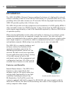
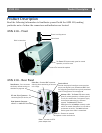
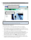
AXIS 230 - Front
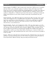
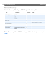
AXIS 230 - Rear Panel
The internal microphone
The Status LED shows steady green for normal
operation, or red for errors
Swivel head
Screw-in ceiling mount
Built-in zoom lens
RS-232 Serial Connector - For
connecting Pan/Tilt devices, etc.
Reset Button - Press to restore
the factory default settings, as
described on page 38.
RJ45 Network Connector -
10BaseT or 100BaseTX Ethernet.
Video Out - Standard BNC connector
allowing direct monitoring of the cam-
era’s image.
Audio in - Connects an external
microphone or other audio device.
Power - connect the PS-K
power adapter here.
Indicator LEDs - The Power LED shows steady
green for normal operation, or flashes green or
is unlit for a malfunction in the power supply.
It also flashes amber during a firmware
upgrade. The Network LED flashes
amber/green for 10/100Mbps network, or solid
red for no network connection. An unlit indica-
tor denotes no activity. The Audio indicator
flashes green when audio is transmitted.
Terminal Block
Provides the physical interfaces to one transistor
output, two digital inputs, RS-485 and GND. Used
for connecting external devices typically associated
with CCTV equipment. See also page 49.