


AXIS Q6035 PTZ Dome Network Camera
Technical Specifications
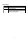
Function/group
Item
Specifications
VCCI Class B
C-tick AS/NZS CISPR 22
KCC Class B
EN/IEC 60950-1
IEC 60529 IP52
IEC 60721-4-3 Class 3K3, 3M3, EN/IEC 60068-2
Midspan: EN 60950-1, GS, UL, cUL, CE, VCCI, CB, KCC, UL-AR
Weight
Camera: 2.6 kg (5.7 lb.)
Camera with drop-ceiling mount: 3.2 kg (7.1 lb .)
Included
accessories
AXIS T8123 High PoE Midspan 1-port, mounting kit for hard and drop ceilings, smoked
dome c over, Installation Guide, Installation and Management Software CD, Windows
decoder 1-user license
Video
management
software
AXIS Camera Companion (software included on CD) — Basic surveillance for small
businesses, where video is recorded to edge storage
AXIS Came ra Station (sold separately) — Fully featured surveillance for medium-sized
installations, where video is recorded on a system s erver
For more information and software applications from partners, see
www.axis.com/products/video/software/
Optional
accessories
Multi-connector cable
Mounting Accessories
Video Surveillance Control Board
Illuminators
Installation Display
Multi-user d ecoder license pack
Midspan
Multi-Connector Cable (sold separately)
When connecting external equipment to the Axis product, a multi-connector cable (available from Axis) is required in order to
maintain the product’s IP rating. The multi-co nnect or cable can be purchased from your Axis reseller.
Connect the multi-connector cable to the product’s multi-connector (see
page 5
). The cable provides the following connectors:
Note
See
page 56
for technical specifications.
Power connector - 3-pin terminal block used for power input. See image below.
Audio in (pink) - 3.5 mm input for a mono m icrophone, or a line-in m ono signal (left channel is used from a stereo signal).
Audio out (green) - 3.5 mm output for audio (line level) that can be connected to a public address (PA) system or a n a ctive speaker
with a built-in amplifier. A pair of headphones can also be attached. A stereo connector must be used for the audio out.
I/O terminal connector - Use in applications for e.g. motion detection, event triggering, time lapse recording and alarm notifications.
In addition to an auxiliary powe r and a GND pin, the I/O terminal connector provides the interface to:
• Digital output — For connecting external devices such as relays and LEDs. Connected devices can be activated by the
VAPIX® Application Programming Interface, output buttonsontheLiveViewpageorbyanActionRule.Theoutput
will show as a
ctive (shown under System Options > Port & Devices > Port Status) if the alarm device is activated.
•Digitali
nput — An alarm input for connecting devices that can toggle between an open and closed circuit, for
example: PIRs, door/window contacts, glass break detectors, e tc. W hen a signal is received the state changes and
the input becomes active (shown under System Options > Port & Devices > Port Status).
58