


AXIS P1343 Network Camera
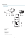
Hardware overview
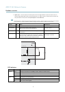
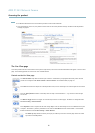
Connectors
Network connector - RJ-45 Ethernet connector. Supports P ower over Ethernet (PoE).
Caution
To protect the product against power surges, a shielded network cable (STP) must be used between the product and the
network switch. Ensure that the network switch is properly grounded.
Audio in (pink) - 3.5 mm input for a mono microphone, or a line-in mono signal (left channel is used from a stereo signal).
Audio out (green) - 3.5 mm output for audio ( line level) that can be connected to a public address (PA) s ystem or an active speaker
with a built-in a mplifier. A stereo connector must be used for the audio out.
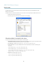
SD card slot - A standard or high-capacity SD card (not included) can be used for local recording with removable storage. For
instructions on how to insert and remove an SD card, please refer to the Installation G uide.
Note
Before removal, the SD card should be unmounted to prevent corruption of recordings. To unmount the SD card, go to Setup
>SystemOptions>Storage>SDCardand click Unmount.
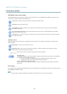
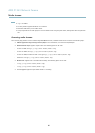
Control button - The control button is used for:
• Enabling the Focus A ssistant. Press and very quickly release the C ontrol button.
• ConnectingtoanAXISVideoHostingSystemservice.Seepage 41. To connect, p ress and hold the button for about
1 second until the Status LED flashes green.
• ConnectingtoAXISInternetDynamicDNSService.Seepage 41. To connect, press and hold the button for
about 3 seconds.
• Resetting the product to factory default settings. See page 47.
Power connector - 2-pin terminal block for power input.
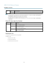
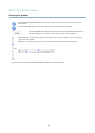
I/O connector
DC power input
Note
For technical specific
ations, see page 54.
I/O terminal connector - Use in applications for e.g. motion detection, event triggering, time lapse recording and alarm notifications.
In addition to an auxiliary power and a GND pin, the I/O terminal connector provides the interface to:
• Digital output
— For connecting external devices such as relays and LEDs. Connected devices can be activated by
the VAPIX® Application Prog ramm ing Interface, output buttons on the Live View page or by an Action Rule. The
output will show as active (shown under System Options > Ports & Devices) if the ala rm device is activate d.
6