


AXIS P1343 Network Camera
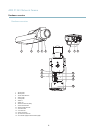
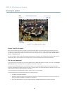
Hardware overview
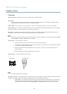
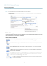
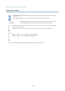
• Digital input — An alarm input for connecting devices that can toggle between an open and closed circuit, for
example: PIRs, door/window contacts, glass break detectors, etc. When a signal is received the state changes and
the input becomes active (shown under System Options > Ports & Devices).
Note
The I/O connector is connected to the housing (fan/heater) on delivery, an d will trigger an input port event to ind icate
a fan or heater error when activated. See Events, on page 33 for information on how to set up an event.
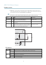
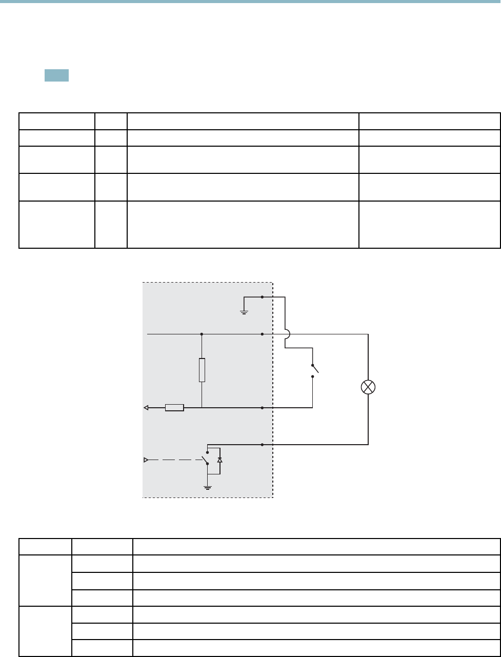
Function Pin Notes
Specifications
GND
1
Ground
3.3 V DC Power
2
Can be used to power auxiliary equipment.
Note: This pin can only be used as power out.
Max load = 50 mA
Digital Input
3
Connect to GND to activate, or leave floating (unconnected)
to deactivate.
0to+40VDC
Digital Output
4
Internal connection to ground when activated, floating
(unconnected) when deactivated. If used with an inductive
load, e.g. a relay, a diode must be connected in parallel with
the load, for protection against voltage transients .
Max load =100 mA
Max voltage = +40 V DC
3.3 V max 50 mA
1
2
3
4
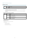
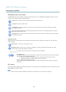
LED indicators
LED
Color
Indication
Green
Steady for conne
ction to a 100 MBit/s network. Flashes for network activity.
Amber
Steady for connection to a 10 MBit/s network. Flashes for network activity.
Network
Unlit No network connection.
Green Steady green for normal operation.
Amber
Steady during startup and when restoring settings.
Status
Red
Slow flash for failed upgrade.
7