


AXIS M1014 Network Camera
Hardware Overview
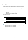
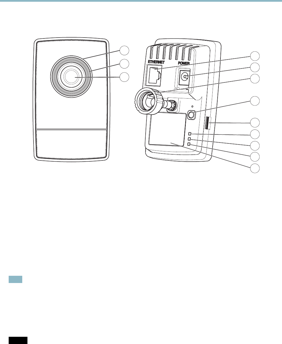
Hardware Overview
4
5
6
7
9
8
12
11
10
2
1
3
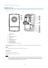
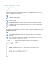
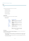
1
Status LED indicator
2
Focus ring
3
Lens
4
Network connector (RJ-45)
5
Power connector
6
Lock ring
7
Control button
8
SD card slot (microSDHC)
9
Power LED indicator
10
Network LED indicator
11
LED indicator (not used)
12
Part number (P/N) & Serial number (S/N)
The Axis product is equipped with a lens with manual focus. It is delivered with the lens prefocused a nd manual focusing is
usually not required.
Note
Only change the focus if required, for example if the im age is blurry.
Connectors
For technical specifications, see
page 46
.
Network connector - RJ-45 Ethernet connector.
NOTICE
Due to local regulations or the environmental and electrical conditions in which the p roduct is to be used, a shielded
network cable (STP) may be appropriate or required. A ny network cab les that a re routed in outdoor environments or similar
sha
ll be shielde d (STP) and intended for their specific use. Make sure that the network switch is properly grounded. See
Electromagnetic Compatibility (EMC)
for regulatory requirements.
4