


AXIS V5915 PTZ Network Camera
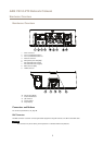
Hardware Overview
HDMI Connector
The HDMI
TM
Connector is used for connecting to a display or monitor.
Network Connector
RJ45 Ethernet connector.
NONO
NO
TICETICE
TICE
Due to local regulations or the environmental and electrical conditions in which the product is to be used, a shielded network
cable (STP) may be appropriate or required. All cables connecting the product to the network and that are routed outdoors
or in demanding electrical environments shall be intended for their specic use. Make sure that the network devices
are installed in accordance with the manufacturer’s instructions. For information about regulatory requirements, see
Electromagnetic Compatibility (EMC) on page 2 .
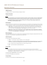
I/O Connector
Use with external devices in combination with, for example, tampering alarms, motion detection, event triggering, time lapse recording
and alarm notications. In addition to the 0 V DC reference point and power (DC output), the I/O connector provides the interface to:
• Digital output – For connecting external devices such as relays and LEDs. Connected devices can be activated by the
VAPIX® Application Programming Interface, output buttons on the Live View page or by an Action Rule. The output will
show as active (shown under System Options > Ports & Devices) if the alarm device is activated.
• Digital input – An alarm input for connecting devices that can toggle between an open and closed circuit, for example:
PIRs, door/window contacts, glass break detectors, etc. When a signal is received the state changes and the input becomes
active (shown under System Options > Ports & Devices).
Power Connector
2-pin terminal block for power input. Use a Safety Extra Low Voltage (SELV) compliant limited power source (LPS) with either a rated
output power limited to ≤100 W or a rated output current limited to ≤5 A.
Audio Connector
The Axis product has the following audio connectors:
• Audio in – 3.5 mm input for a stereo microphone, or a line-in stereo signal.
• Audio out – 3.5 mm output for audio (line level) that can be connected to a public address (PA) system or an active speaker
with a built-in amplier. A pair of headphones can also be attached. A stereo connector must be used for audio out.
• Left – 3-pin XLR connector for balanced audio input. Use left connector for mono.
• Right – 3-pin XLR connector for balanced audio input.
SD Card Slot
NONO
NO
TICETICE
TICE
• Risk of damage to SD card. Do not use sharp tools or excessive force when inserting or removing the SD card.
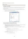
• Risk of data loss. To prevent data corruption, the SD card should be unmounted before removal. To unmount, go to Setup >
System Options > Storage > SD Card and click Unmount.
This product supports SD/SDHC/SDXC cards (not included).
For SD card recommendations, see www.axis.com
Control Button
For location of the control button, see Hardware Overview on page 7 .
8