


20 en | Mounting MIC Series 500 Camera
F.01U.173.601 | 2.0 | 2010.11 User’s Manual Bosch Security Systems, Inc.
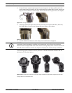
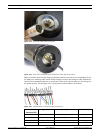
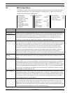
Figure 4.13 Composite cable before connection
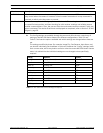
Figure 4.14 View of the Composite Cable connected to a MIC 500 Series camera
Refer to the MIC Series Power Supply Installation Manual included on the Installation CD for
full details on installing a MIC Series Power Supply Unit and connecting to a MIC 500 Series
Camera.The composite cable has no termination (free wires) at the other end for wiring into
the power supply. The standard color coding used in these cables is as follows:
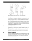
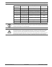
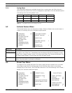
Figure 4.15 Exploded View of Composite Cable Connections
Camera Cable
Connector Pin
Signal Name Description Cable Wire Color
1 Washer Drive Rtn Auxiliary Connection Grey
2 Tamper Sw Rtn Auxiliary Connection Brown
3 Washer Drive Wash Signal Orange
4 Tamper Sw Alarm Communications Black