


MIC Series 500 Camera Navigating the Menus | en 35
Bosch Security Systems, Inc. User’s Manual F.01U.173.601 | 2.0 | 2010.11
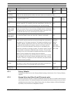
5.8.1 Alarm Relays and Re-arm Time
The multi alarm card also provides 2 output relays which the camera activates under certain
programmable circumstances. The options are as follows:
For example, if alarm input 4 triggers the PSU, it can be configured to close relay 1 and open
relay 2, or open relay 1 and do nothing with relay 2, etc. This is a way of providing the alarm
information to other equipment or resetting the alarm which has activated.
The alarm rearm time allows the user to set a time between sequential triggers of the same
alarm, and for how long the relays are set to their activated state. This can be set to 1, 5, 10 or
60 seconds.
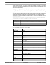
5.9 Sony Set Menu
The Sony Set menu enables the user to adjust camera settings such as: white balance, gain,
sharpness, sync, backlight, and shutter. The Sony Set menu stores up to ten (10) Sony Set
tables, each containing ten (10) separate camera controls. A complete setup for the camera
module (shutter speed, gain level, effect, etc.) can be saved and reloaded via a user’s input,
as compared to having to modify each setting separately.
These can also be mapped to a MIC 500 Series Camera function, such as a preset number,
alarm input, or normal running, enabling the user to set up an ANPR mode or similar at a given
preset position, or set the camera to a fixed shutter speed when a given alarm goes off.
As soon as the camera moves from a position where a mode has been loaded, it loads the
Sony Set which is mapped to normal running, returning the camera to its standard state.
Additionally, there is an option to map to nothing; these can be called as and when required
using the learn preset command associated with the Sony Set table.
Note: Mapping a Sony Set table to a given function may cause a slight delay before the desired
function is carried out, depending on the number of actions stored in the table.
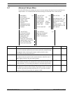
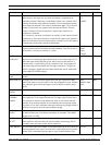
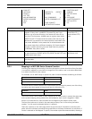
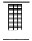
MANUAL CONTROL Enables you to control the unit manually. N/A
LEARN ALARM POS Configure the tamper alarm or individual multialarm positions. AUTO ALARM
POS OR 1 TO 12
RELAY 1 & 2 STATUS See Section 5.8.1 Alarm Relays and Re-arm Time, page 35. Normally Open/
Normally Closed
NORMALLY CLOSED Disconnects the circuit when the relay is activated; the circuit is
connected when the relay is inactive.
N/A
NORMALLY OPEN Connects the circuit when the relay is deactivated; the circuit is
connected when the relay is active.
N/A
(RELAY 1) SET WITH
ALARM
See Section 6.8.1 Alarm Relays and Re-arm Time, Page 41. Inputs 1 - 4 / Any
Alarm
(RELAY 2) SET WITH
ALARM
See Section 6.8.1 Alarm Relays and Re-arm Time, Page 41. Inputs 5 - 8 / Any
Alarm
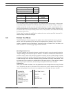
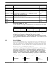
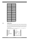
Menu Item Description Options
Relay 1 Relay 2
Relay Activation Any Alarm Input Alarm Inputs 1 - 4 Any Alarm Input Alarm Inputs 5 - 8
Relay State Normally Open Normally Closed Normally Open Normally Closed
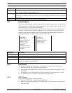
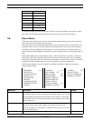
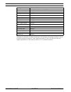
MAIN MENU 2/2 SONY SET SETUP
COMMANDS