


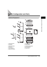

System Configuration and Parts
1-12
Before You Start Using This Machine
1
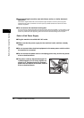
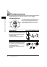
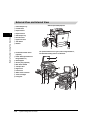
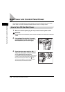
External View and Internal View
a Centre Output Tray
b Control Panel
c Paper Drawer 1
d Paper Drawer 2
e Side Output Tray
f Exit Slot Cover
g Upper Left Cover
h Test Button
i Breaker
Without Optional Equipment
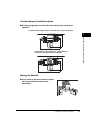
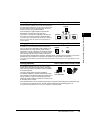
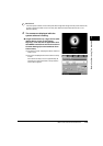
j Underside of Platen Cover
(optional)
k Platen Glass (optional Color
Image Reader-C1)
l Stack Bypass
m Security Key (optional)
n Main Power Switch
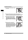
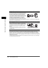
o Transport Unit
p Right Cover
q Front Cover
r Waste Toner Container
s Toner Cartridges
t Fixing Unit
The optional Platen Cover Type G, Color Image Reader-C1,
and Cassette Feeding Unit-X1 are attached.