2-4
Before Using the VB-C10/VB-C10R
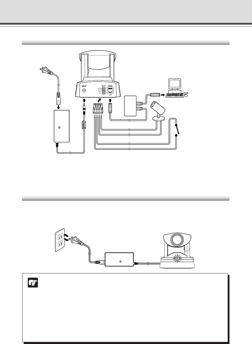
Connecting the Components
Turning the Power ON and OFF
The VB-C10/VB-C10R itself does not have a power switch. You can switch the VB-C10/VB-C10R
on by plugging the AC adapter into a wall outlet. When power to the VB-C10/VB-C10R is switched
on, the Camera LED turns green.
Note
● The camera head position is automatically initialized when the power supply is
turned ON from OFF.
● Never touch the camera head during initialization as this could prevent
successful initialization and cause faults.
● Wait at least five seconds before turning the power back on after shutting it off.
Turning it on too quickly may result in a malfunction. Observe the precautions
given in “a Safe Use of Equipment/a IMPORTANT SAFETY INSTRUCTIONS”
(→ P.ix).
● If the picture recording function (→ P.3-16) is being used, shutting off the
power or restarting the VB-C10/VB-C10R will cause all pictures to be deleted.
External input device
(sensor, etc.)
External output device
LAN
cable
Cables for external device
*
AC cable
(Rear of main unit)
AC adapter
Hub
PC
AC cable
to AC outlet
AC adapter
Main unit
*Remove some insulation at the end of the external device cable and insert it into the plug for the
external device, then secure it by tightening the screws. See page 6-2 for examples of external
device connections.


