


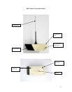
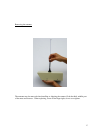
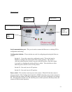

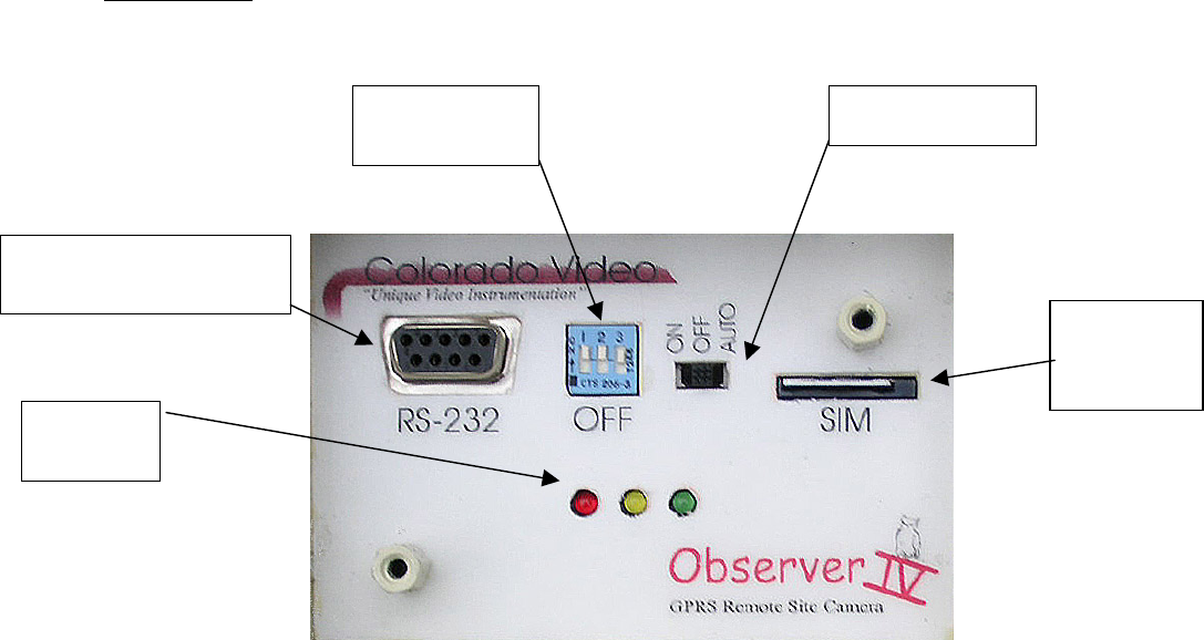
The back panel
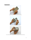
Serial communications port
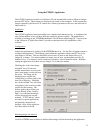
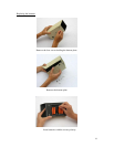
Configuration
switches
Status
LEDs
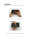
Power switch
Subscriber
Identity
Module slot
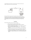
Serial communications port – This port is used to connect the Observer to a desktop PC for
configuration and testing.
Configuration Switches – These switches are used for configuring and testing the Observer
camera.
Switch #1 - Forces the camera into configuration mode. This switch must be
DOWN to configure the camera and UP for normal operation. The switch is
valid only when the power switch is moved to the ON position. Once the camera
is powered on, changing the switch will have no effect. The switch has no effect
when the power switch is in the AUTO position.
Switch #2 – Not used, leave in UP position.
Switch #3 – Not used, leave in UP position.
Power switch – This switches controls power to the camera. When ON (left) the camera is
always powered. If the Configuration Switch #1 is DOWN when the power switch is placed to
the ON position the camera will enter configuration mode, and can be configured via a desktop
PC. If Configuration Switch #1 is UP when the power switch is placed to the ON position, the
camera will enter normal operation.
21