


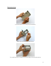
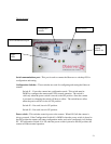
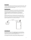

Power connections
An external DC power supply may be connected to pins 1 and 2 of the external connector. Make
sure the power supply meets the requirements outlined in Appendix B. When the external power
connections are used, the internal power selector switch must be set properly. Do not reverse
power supply leads; the camera will be damaged.
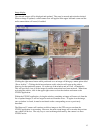
External trigger operation
The external trigger line allows the camera to be activated by an external switch closure
(door/gate switch or a motion detector). The operation is the same in both AUTO and
ON power modes, except in AUTO mode the camera will automatically turn on and off
in response to the trigger signal, conserving battery power. The camera is always
powered in the ON mode. The external trigger function is always available; no
configuration settings are required. Do not connect to this signal if this function is not
required.
The external trigger line must be switched to the ‘return’ line for a minimum of 300
milliseconds to activate the camera. In AUTO mode the external trigger must be released
from the ‘return’ connection before the camera will turn back off. If the external trigger
line remains connected to the ‘return’ the camera will remain powered. Do not hook this
signal up to anything other than ‘dry’ (un-powered) switch contacts.
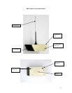
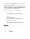
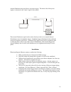
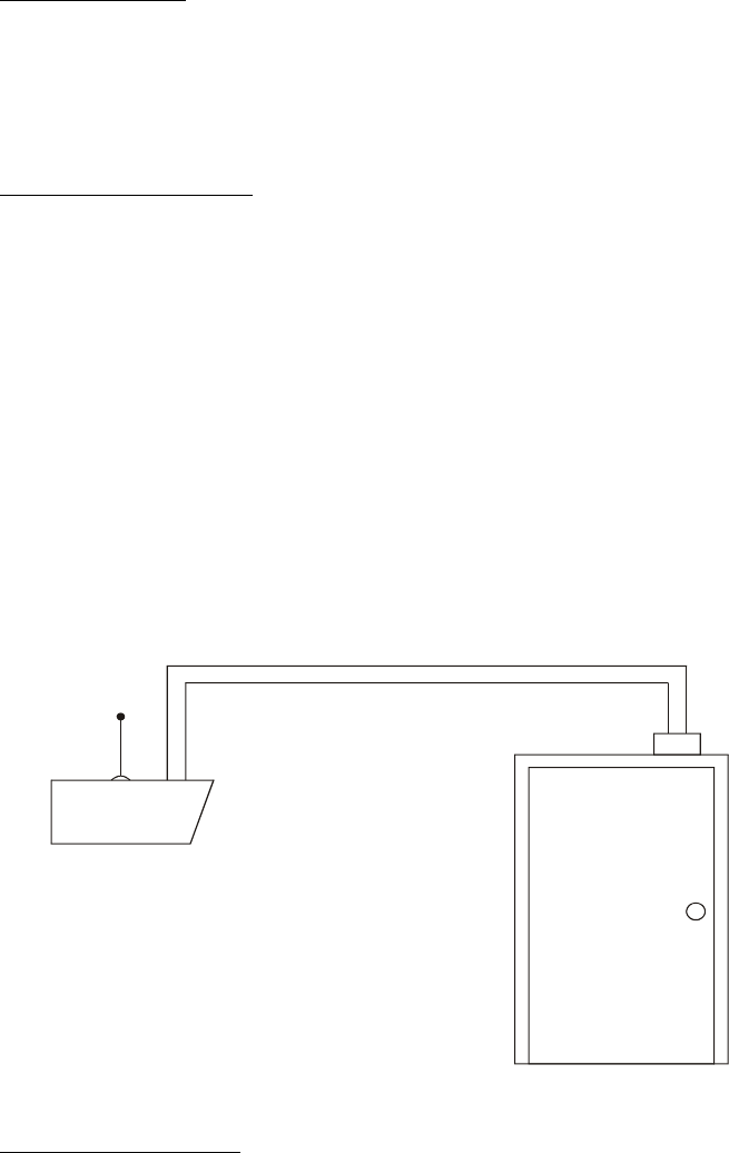
Observer Camera
Switch closes
when door opens.
External Trigger
Return
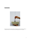
External lighting control
The external lighting control provides a signal that can turn on an external illuminator.
When enabled, via the check box on the Camera Settings configuration page this signal
will become active when the auto exposure algorithm detects a low light condition. The
exposure will be made one second after the signal becomes active.
The signal provides the return path (- side) for a DC power supply. The signal can sink
up to 1.5 amperes at 30 volts DC. Exceeding these limits will damage the unit. The
23