


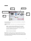

When the power switch is in the AUTO (right) position the camera is normally un-powered. It
will turn on in response to an external trigger signal or to a previously scheduled time.
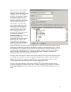
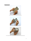
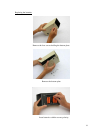
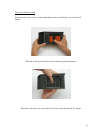
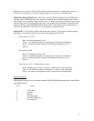
Subscriber Identity Module slot – This slot accepts the SIM card supplied by the GSM service
provider when a GPRS data account is obtained. Insert the card with the copper contacts down,
push all they way in until the locking action is felt. To remove the card, push all they way in until
the unlocking action is felt and remove the card. The camera cannot transmit information to the
Internet without a valid GSM/GPRS SIM in this location. The camera can be configured via a
web browser without this card, however, it will unable to transmit pictures.
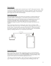
Status LED’s – These LED’s indicate the status of the camera. Their function differs slightly
depending on the position of the power mode and Configuration Switch #1.
Power mode = AUTO
Red – On when the camera is ON
Yellow – On while the camera is attempting to connected to the Internet.
Green – Flashing while the camera is transmitting information to the
Internet.
Power mode = ON
.
Red – On when the camera is ON
Yellow – On while the camera is attempting to connected to the Internet.
Green – Flashing while the camera is transmitting information to the
Internet.
Power mode = ON – Configuring the camera.
Red – Blinking when trying to connect to a desktop PC via the serial port.
Yellow – On while the camera is attempting to connect to the desktop PC.
Green – On when the computer has made a connection to the desktop PC
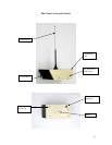
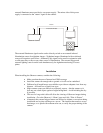
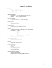
External connector
The external connector is a 6 pin Hirose receptacle (HR-30-6R-6P) and mates with a 6 pin Hirose
plug (HR30-6P-6S).
Pin # Signal
1 +DC power
2 Ground
3 Return
4 External trigger
5 External illuminator
6 No connection
22