


1-4
Cisco Video Surveillance 6020 IP Camera Installation Guide
OL-28120-02
Chapter 1 Overview
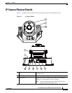
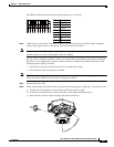
IP Camera Physical Details
4 Tilt adjustment screw Used when tilting the camera to set the field of view.
5 Recessed Reset button Recessed button that reboots the IP camera or resets it to a
default state. You can use a pin or paper clip to depress it. It can
be used any time that the IP camera is on and can have various
effects, as described in the
“Resetting the IP Camera” section
on page 4-4.
6 Microphone and Video Output
switches
Microphone
• Off (up)—Disables an external microphone connected to
the IP camera.
• On (down)—Enables an external microphone connected to
the IP camera.
Video Output
• NTSC 60Hz (up)—Switches camera operation to the
National Television System Committee (NTSC) standard.
• PAL 50Hz (down)—Switches camera operation to the
Phase Alternating Line (PAL) standard.
7 micro SD card slot Supports up to 8 GB of video data on a micro SD memory card
when the camera loses network connectivity.
8 Audio/Video out (green) Allows the connection of an optional Y cable or mini cable with
BNC connector. You can connect a video monitor to the mini
cable with BNC connector. Both cables are included in the
optional audio/video cables accessory kit can be purchased
from Cisco (Cisco part number CIVS-AVCABLE).
9 Microphone In (pink) Connection for an external microphone.
10 Ethernet 10/100 RJ45 socket Accepts a standard LAN cable to connect the IP camera to a
10/100BaseT router or switch.
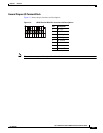
11 GPIO Terminal Block General purpose input/output (GPIO) terminal block that is
used to connect external input and output devices. For more
information, see
Figure 1-2.