


45
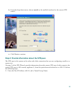
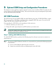
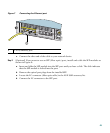
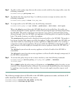
Figure 7 Connecting the Ethernet port
c. Connect the other end of the cable to your network device.
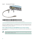
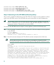
Step 2 (Optional) If you want to use an SFP (fiber optic) port, install and cable the SFP modules as
shown in Figure 8:
a. Insert and slide the SFP module into the SFP port until you hear a click. The click indicates
that the SFP module is locked into the port.
b. Remove the optical port plugs from the installed SFP.
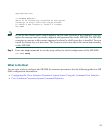
a. Locate the LC connector (fiber optic cable) in the 4GE SSM accessory kit.
b. Connect the LC connector to the SFP port.
1 RJ-45 (Ethernet) port
143597
MGMT
USB2
Cisco SSM-4GE
LNK
SPD
0
1
2
3
POWER
STATUS
MGMT
USB2
USB1
Cisco SSM-4GE
1