


7
Step 3
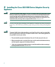
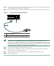
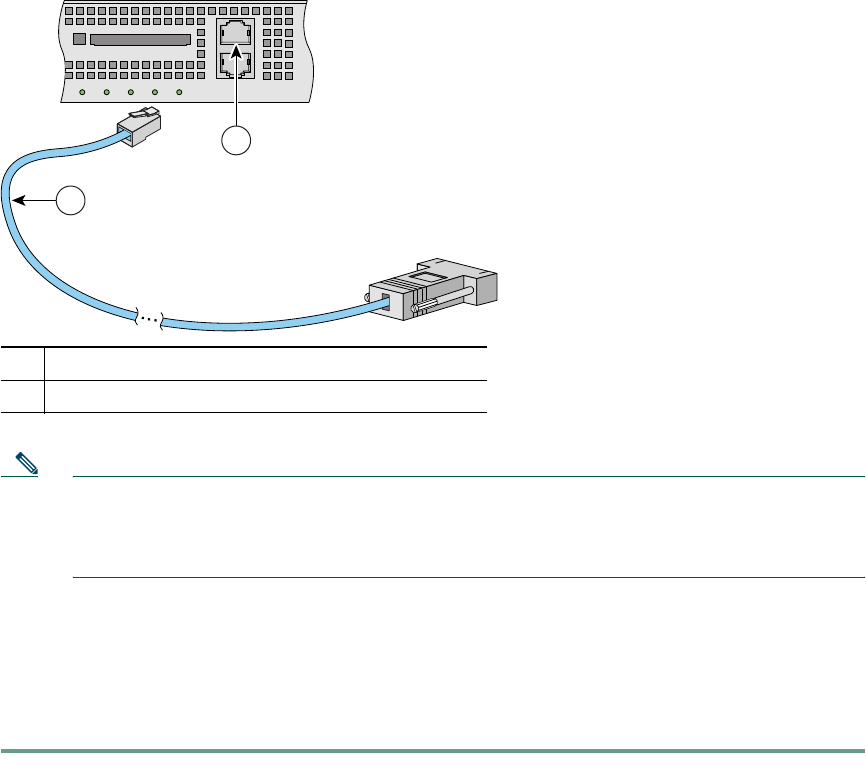
Connect the RJ-45 connector of the blue console cable to the Console port on the rear panel
of the adaptive security appliance. (See Figure 3.)
Step 4 Connect the DB-9 connector of the blue cable to the serial port on your computer or terminal.
Figure 3 Connecting the Chassis Console Cable
Note Alternatively, for management purposes, you can also connect an Ethernet cable to the
adaptive security appliance MGMT port. The MGMT port is a Fast Ethernet interface designed
for management traffic only and is specified as Management0/0. The MGMT port is similar to the
Console port, but the MGMT port accepts only incoming traffic.
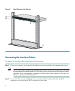
Step 5 Locate the yellow Ethernet cable in the accessory kit.
Step 6 Attach one end of the Ethernet cable to an Ethernet port and the other end to a network
device, such as a router, switch, or hub.
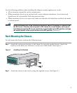
Step 7 Attach the power cord to the adaptive security appliance and the power source.
Step 8 Power on the chassis.
1 RJ-45 console port
2 RJ-45 to DB-9 serial console cable (null modem)
92593
FLASH
CONSOLE
AUX
POWER
STATUS
FLASH
VPN
ACTIVE
2
1