


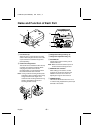
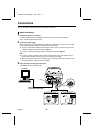
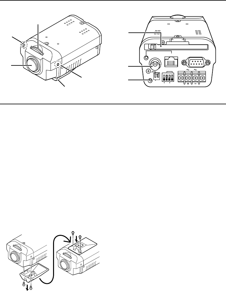
Name and Function of Each Part
PC CARD
RS-232C
ALARM IN OUT
MODEM
PC
COM
AC24V
DC12V
GND
1 2
ETHERNET
POWER
MONITOR
OUT
5
6
7
4
1
2
3
3
CLASS 2 WIRING
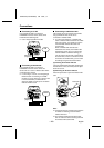
1
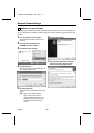
Lens mount cap
Attach this cap to protect the lens mounting
section. When using the camera, remove the
cap and attach the automatic iris-type lens
(sold separately).
2
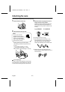
Camera mounting bracket
This bracket can be installed to either the top
or bottom of the camera as desired. When
changing the position of the camera
mounting bracket, you should always reuse
the screws that have been removed.
Note: If using a camera mounting bracket (sold
separately), select a location that is strong
enough to bear the full weight of the
camera and the mounting bracket for long
periods, and install the camera and
mounting bracket securely.
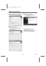
3
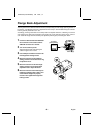
Flange back locking screws (p. 8)
4
Flange back adjustment dial (p. 8)
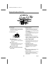
5
PC CARD slot
Use this slot to insert a memory card or
wireless LAN card.
Note: Make sure that the camera’s power is
turned off before inserting the card.
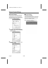
6
MONITOR OUT connector
When setting up the camera, use this
connector to connect the camera to the
VIDEO IN connector of a monitor for
adjusting the angle of view and focus.
7
POWER indicator
This indicator illuminates when 24 V AC or
12 V DC is being supplied to the power input
terminals of the camera.
L5AB2/US (VCC-WB2000) GB 2002, 7, 4
English
– 5 –