


SKU 67139 For technical questions, please call 1-800-444-3353. Page 11
SETTING UP THE DVR WITH
A TV MONITOR
DVR/CAMERA CONNECTIONS
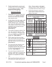
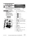
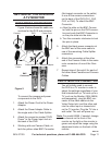
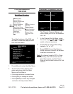
Figure 5 below shows the cable con-
nections for the DVR and cameras.
BNC
Connector
Camera
Power Adapter
Power Cord
Camera
Cable
Cable Splitter
DVR
Figure 5
1
6
2
3
5
4
4a
4b
To connect the camera and power
components to the DVR:
Attach the Power Cord to the Power 1.
Adapter.
Attach the Power Adapter Cable to 2.
the single end of the Cable Splitter.
Attach the connector marked “DVR 3.
Power” to the Power Input Jack on
the back of the DVR.
Working with one Camera Cable, at-4.
tach the yellow video BNC Connector
(the largest connector on the cable)
to one of the camera connections
on the back of the DVR (CH1, CH2,
CH3, or CH4). To attach the BNC
Connector:
Align the slots on the BNC Connec-a.
tor with the pins on the DVR connec-
tion and push the BNC Connector in
so the pins slide into the slots.
Turn the connector clockwise to lock b.
the pins in place.
Attach the black power connector at 5.
the BNC end of the same cable to
one of the remaining Cable Splitter
connectors.
Attach the connectors at the other 6.
end of the Camera Cable to the same
color connectors of one of the Cam-
eras.
Repeat steps 4 through 6 for each of 7.
the other three Cameras and Camera
Cables.
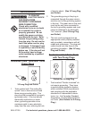
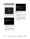
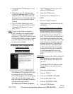
DVR/TV MONITOR CONNECTION
You will initially need to connect
the DVR to a TV monitor in order to
adjust the settings regardless of your
TV, such as the Monitor (SKU 66556,
sold separately), plug the BNC con-
nector of the video cable into the
into the video Input or channel slot
on the TV monitor. Plug the TV into a
wall outlet. The unit will power up.
Note: For model 66556, if needed, change
the channel on the front of the
monitor so the light on the monitor is
green and adjust the image using the
adjustment knobs on the back of the
monitor.
REV 10h