


SKU 94634 For technical questions, please call 1-800-444-3353 PAGE 10
PRODUCT OVERVIEW
The Curb Machine is an electrically-driven concrete extruder.
The machine operates on common household current of 115 volts.1.
The machine produces continuous concrete edging, borders, and mower strips 2.
without the use of form work or guide rails.
The machine can produce in excess of 500 feet per hour under ideal conditions 3.
with constant feeding.
The machine can create circles with a diameter of 36 inches, and will lay the con-4.
crete product as close as 1/4 inch from an existing structure.
The machine can also extrude the edging in a trench or above the ground as 5.
needed.
PRODUCT FEATURES
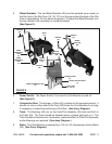
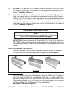
Body Assembly: 1. The Body (13) includes the Hopper, Motor Enclosure, and Chute.
(See Figure E, next page.)
Steering Assembly: 2. The Steering Assembly is located at the rear of the Curb
Machine and includes the Steering Handle (46), Steering Rod (43), Wheel Bracket
(47), and rear Pneumatic Tires (9) for lateral movement of the entire unit.
(See Figure E.)
The Steering Assembly is usually centered if you are working on level ground with
no obstacles. If you are performing landscape curbing with trenches, garden areas,
etc., the Steering Assembly is moved so that the left Pneumatic Tire (9) goes in the
trench and the right Pneumatic Tire goes on the grass side. The Curb Machine can
be operated with the Steering Assembly centered or off to the left or off to the right
depending on the conditions. (See Figure E.)
Front Pneumatic Tire: 3. The Front Pneumatic Tire (9) is located on the right/front of
the Curb Machine and is only used to transport the machine. The front Pneumatic
Tire (9) should be installed upside down while curbing. To do so, loosen the Lock-
ing Knob (6). Slide the front Pneumatic Tire with its Front Tire Rod Assembly (7)
out from the Body (13) of the unit. Insert the Front Tire Rod Assembly with its front
Pneumatic Tire upside down into the Body. Then, retighten the Locking Knob.
(See Figure E, and Assy. Diagram.)
Slip Forms: 4. The Slip Forms (1A, 1B, 1C) produce the desired shape of the curb.
They come in 4 inch by 6 inch wide sizes. To install a Slip Form, align the mounting
holes in the Slip Form with the mounting holes located in the front/bottom of the
Body (13). Then secure the Slip Form in place, using the Bolts (5), Spring Washers
(4), Flat Washers (3), and Lock Nuts (2).
(See Figure E, and Assy. Diagram.)