


SKU 94634 For technical questions, please call 1-800-444-3353 PAGE 11
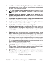
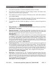
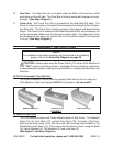
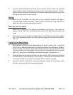
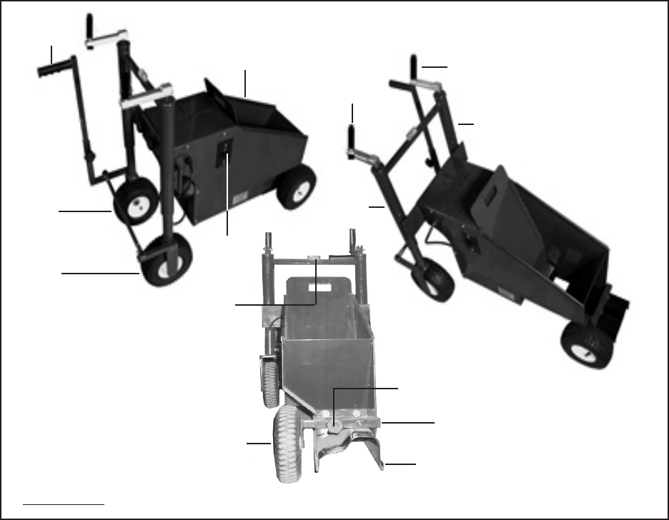
Wheel Brackets: 5. The two Wheel Brackets (28) must be adjusted (up or down) so
that the front of the Slip Form (1A, 1B, 1C) is on the ground and the back of the Slip
Form is raised about 1/4 inch above the ground. To adjust the Wheel Brackets, turn
the two Handles (34) clockwise or counterclockwise.
(See Figure E.)
LOCKING KNOB
(6)
FRONT PNEUMATIC TIRE
(9)
HANDLE
(34)
HANDLE
(34)
SLIP FORM
(1A, 1B, 1C)
BODY
(13)
FRONT TIRE ROD ASSY.
(7)
WHEEL
BRACKET
(28)
WHEEL
BRACKET
(28)
STEERING
HANDLE
(46)
REAR
PNEUMATIC
TIRE
(9)
REAR
PNEUMATIC
TIRE
(9)
POWER
SWITCH
(14)
FIGURE E
LEVELER
(42)
6. Power Switch: The Power Switch (14) turns the Curb Machine on and off.
(See Figure E.)
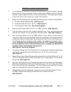
Compaction Ram: 7. The plunger, or Ram (64), pushes out the concrete product. It
should not rub on either side of the Track (63) when the Curb Machine is running.
If necessary, re-adjust the positioning of the Ram. (See Assy. Diagram.)
Track: 8. The Bearings (58) run on the Push/Pull Assembly (59) back and forth in
the Track (63). The Track should be replaced when a groove gets worn in it. The
Track should be checked and, if necessary, replaced when the Push/Pull Assembly
and/or Bearings are replaced. (See Assy. Diagram.)
Motor: 9. The Curb Machine is powered by a 115 volt, 3/4 Horsepower, electric Motor
(25). (See Assy. Diagram.)