


SKU 94634 For technical questions, please call 1-800-444-3353 PAGE 12
ASSEMBLY INSTRUCTIONS
NOTE:
For additional information regarding the parts listed in the following
pages, refer to the Assembly Diagram on page 22.
CAUTION! Always make sure the Power Switch (14) for the Curb Machine is
in its “OFF” position and the machine is unplugged from its electrical outlet prior
to assembling the machine, adding any accessories, or making adjustments to the
machine.
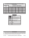
To Fill The Pneumatic Tires With Air:
The three Pneumatic Tires (9) must be properly filled with air prior to using the
Curb Machine. Each tire requires 30 PSI of air pressure. Do not overfill.
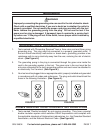
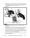
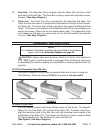
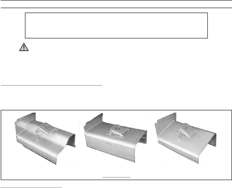
MOWER’S EDGE (1A)
CURB STYLE (1C)
SLANT STYLE (1B)
FIGURE F
To Install A Slip Form:
The Curb Machine comes with three different styles of Slip Forms: The Mower’s
Edge (1A), the Curb Style (1C), and the Slant Style (1B). To install a Slip Form,
align the mounting holes in the Slip Form with the mounting holes located in the
front/bottom of the Body (13). Then secure the Slip Form in place, using the Bolts
(5), Spring Washers (4), Flat Washers (3), and Lock Nuts (2).
(See Figure F, and Assy. Diagram.)
Gear Box: 10. The Gear Box (24) is located under the Motor (25) and has a shaft
protruding out the left side. The Gear Box is factory sealed and requires no main-
tenance. (See Assy. Diagram.)
Crank Arm: 11. The Crank Arm (53) is connected to the Gear Box (24) shaft. The
Crank Arm has two holes in it to adjust the stroke speed and length of the Compac-
tion Ram (64). The Crank Arm is factory preset on the longest and fastest stroke
length. The Crank Arm is attached to the Gear Box shaft with a key and keyway, as
well as set screws. Make sure the set screws remain tight. The adjustment holes
are threaded so that when you remove the nut, the bolt still needs to be threaded
in or out. (See Assy. Diagram.)