


__ a. Remove or open the back cover on your system unit. See
Appendix A, “Removing the back covers” on page 31 if you need
instructions.
__ b. Find the first set of available HSL connectors on the back of your
system unit.
If you have just one set of HSL connectors on your system unit, they
are labeled A0 and A1.
If you have more than one set of HSL connectors on your system
unit, the first set is labeled A0 and A1. The remaining HSL
connectors are labeled alphabetically. For example, if you have an
830, there are four sets of HSL connectors on your system. They are
labeled A0 and A1; B0 and B1; C0 and C1; D0 and D1.
__ c. Write down which set of HSL connectors are available here: _____ ,
_____.
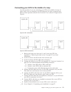
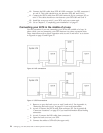
__ 4. Connect one end of an HSL cable that is labeled 0 on both ends to the HSL
connector that you found in step 3c.
For example, if the next available HSL connectors are B0 and B1, connect
the HSL cable to connector B0.
__ 5. Open the back cover on your 5079. See Appendix A, “Removing the back
covers” on page 31 if you need instructions.
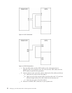
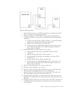
__ 6. On unit 5079–002 locate the HSL connectors that are labeled 0 and 1
(Figure 27 on page 39)
__ 7. On unit 5079–002, install the other end of the HSL cable to the connector
that is labeled 0.
__ 8. On the unit 5079–002, install the end that is labeled 1 on the HSL cable that
is labeled 1 and 0 to the connector that is labeled 1.
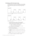
__ 9. On unit 5079-001, install the other end of the HSL cable to the HSL
connector that is labeled 0.
__ 10. On unit 5079-001, install one end of a the HSL cable that is labeled 1 at
both ends to the HSL connector that is labeled 1.
__ 11. Install the other end of the HSL cable to the other HSL connector that you
found in step 3c.
For example, if the next available HSL connectors are B0 and B1, connect
the HSL cable to connector B1.
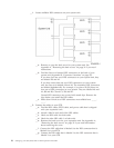
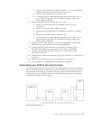
__ 12. On your system unit, install one end of an SPCN cable to an available
SPCN connector. The SPCN connector is labeled J15 or J16.
__ 13. Tighten the thumbscrews.
__ 14. On unit 5079–002, connect the other end of the SPCN cable to the SPCN
connector that is labeled J15.
__ 15. Tighten the thumbscrews.
__ 16. On unit 5079-002, connect another SPCN cable to the SPCN connector that
is labeled J16.
__ 17. Tighten the thumbscrews.
__ 18. On unit 5079-001, connect the other end of the second SPCN cable to the
SPCN connector that is labeled J15.
__ 19. Tighten the thumbscrews.
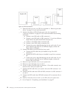
__ 20. On your 5079 connect a power cable to each power connector.
__ 21. Do not plug into an electrical outlet.
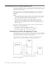
__ 22. Go to Chapter 5, “Completing your installation” on page 27.
Chapter 4. Setting up your 5079 Expansion Unit 21