- 10 -
CV-M10BX/CV-M10RS
7.4.2. Non interlaced mode
With SW1-5 ON the camera is in non-interlaced mode. The video is read out on video 1 as a full progressive scanned frame.
The frame rate can be up to 25 for CCIR and 30 for EIA.
7.5. Gamma Correction
SW 1-6 will select the gamma correction. OFF is gamma 1.0, which is linear and normally used for vision. ON is gamma 0.45,
which is non-linear.
7.6. Gain Control/RS 232C control
SW1-7 and SW1-8 has different functions on CV-M10BX and CV-M10RS.
7.6.1. Gain control on CV-M10BX
SW1-7 OFF and SW1-8 OFF is fixed gain. Here the gain is fixed for the 2 video outputs. Can be adjusted by internal
potentiometers. (See "9. Internal Adjustments.")
SW1-7 OFF and SW1-8 ON is rear potentiometer for gain setting. This will only work on video 1 output.
SW1-7 ON and SW1-8 OFF is the AGC mode. It will only work on video 1 output. The AGC level can be adjusted by an internal
potentiometer. (See "9. Internal Adjustments.")
7.6.2. RS232C control on CV-M10RS
SW1-7 and SW1-8 OFF will enable the settings from the SW1 on rear.
SW1-7 and SW1-8 ON will enable the RS232C serial input for camera control.
Notes:The setting should be done with power off. If the RS camera should be used with rear switch setting, the user setting
from RS232C should be in the normal shutter range.
By shift to the low speed range it can take up to 20 sec. before the camera operates correctly.
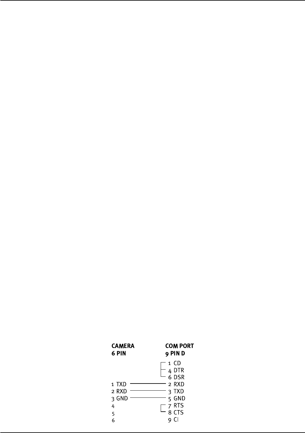
7.7. CV-M10RS Serial Interface for Controls
The RS-232C serial interface specification for CV-M10 is: 9600 Baud, 8 data bit, 1 start bit, 1 stop bit, and no parity.
Functions, which can be controlled by the RS-232C interface, are:
Shutter speed All shutter times as shown in 7.2.2
Trigger select Continuous, Triggered
Scanning mode Interlaced, non-interlaced
Levels Manual gain, AGC level, black level and white clip level
Notes:The following cannot be controlled via RS232C:
Gamma 1.0 - 0.45
Trigger mode: Edge Pre-select, Pulse Width Control, H reset and H non-reset
7.7.1. RS232C Cable Connections


