


- 2 -
CV-M10BX/CV-M10RS
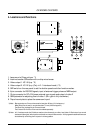
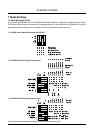
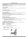
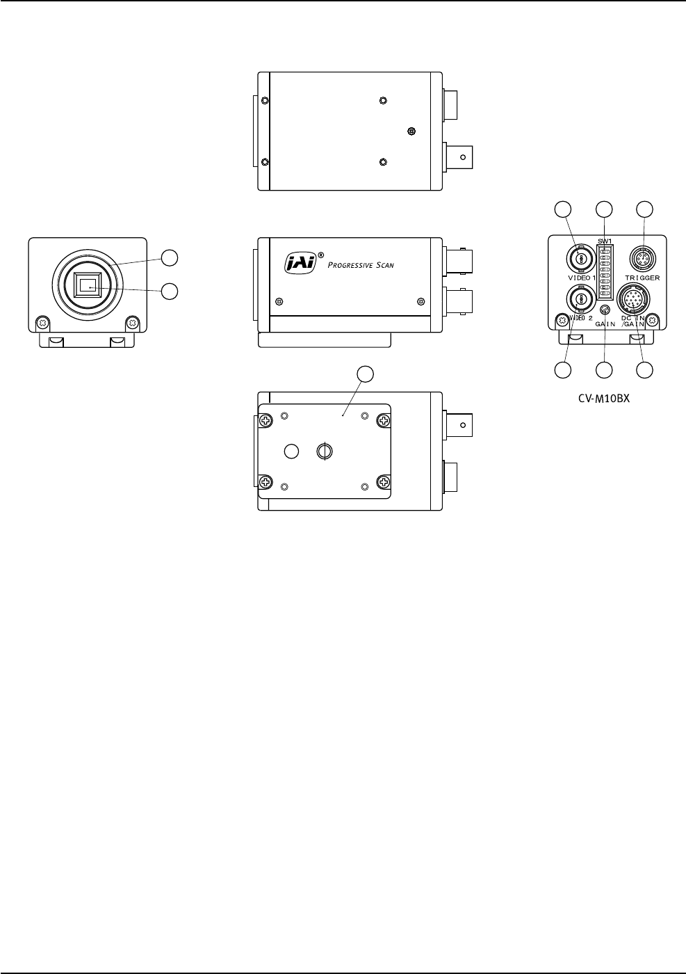
4. Locations and Functions
9
3 5 6
4 8 7
1
2
1. Lens mount of C-mount type. *1)
2. Interline-transfer CCD sensor with on-chip micro lenses.
3. Video output 1. VS 1.0 Vp-p. *2)
4. Video output 2. VS 1.0 Vp-p. (Only in 2 :1 interlaced mode.) *2)
5. SW1 switch on the rear panel to set the shutter speed and other function modes.
6. 6 pin connector for RS 232C signals, input of external trigger pulse and WEN output.
7. 12 pin connector for DC +12V power external sync signals and output of video 2
8. GAIN potmeter for adjusting level of video 1. (Min. gain is fully clockwise.)
9. Tripod mount plate to place the camera on tripod.
*1) Note: Rear protrusion on C-mount lens must be less than 10.0mm (0.4 inch approx.)
When IR cut filter is used, it must be less than 7.0 mm (0.28 inch approx.)
The IR cut filter is placed in the C-mount thread.
The C-mount 25 mm IR cut filter must be ordered separately.
*2) Note: In 2:1 interlace mode the 2 fields are read out simultaneously on video 1 and video 2. Each output is a normal
interlaced video signal, which can be monitored on a normal video monitor. A full progressive scanned frame can
be obtained by combining the 2 outputs in a frame grabber.