


58 EN
CONNECTIONS
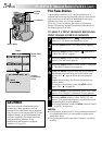
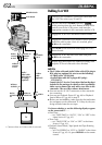
Basic Connections
These are some basic types of connections. When making the connections, refer also to your VCR and TV
instruction manuals.
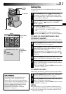
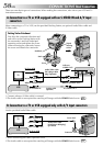
A. Connection to a TV or VCR equipped with an S-VIDEO
IN and A/V input connectors
To S-VIDEO IN
Connector cover*
To S-VIDEO OUT
To TV or VCR
S-Video cable
(optional)
TV
VCR
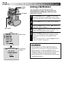
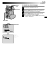
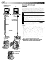
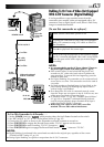
A. Connection to a TV or VCR equipped with an S-VIDEO
Audio/Video cable
[mini-plug to RCA plug]
(provided)
To AV OUT
Red to AUDIO R IN**
TV
VCR
To TV or VCR
White to AUDIO L IN**
* When connecting the cables, open this cover.
** The Audio cable is not required for watching still images with the POWER Switch set to “
M
E
M
O
R
Y
P
L
A
Y
”.
Yellow to VIDEO IN
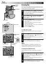
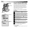
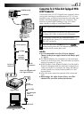
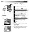
Docking Station Attachment
First align the camcorder direction stud
and screw on the Docking Station with
the camcorder’s stud hole and tripod
mounting socket and tighten the screw.
When removing the camcorder, loosen
the screw and detach the camcorder.
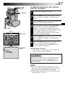
A. Connection to a TV or VCR equipped with an S-VIDEO IN and A/V input
connectors
When connecting to a TV or VCR, use the provided Docking Station, an optional Audio/Video cable and
S-Video cable.
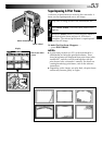
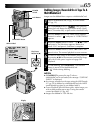
B. Connection to a TV or VCR equipped only with A/V input connectors
Use the provided Audio/Video cable.
Audio/Video cable
[RCA plug to RCA
plug] (optional)
Red to AUDIO R OUT**
White to AUDIO L OUT**
Yellow to
VIDEO OUT*
Red to AUDIO R IN**
White to AUDIO L IN**
Yellow to VIDEO IN*
* Connect when an S-Video cable is not used.
** The Audio cable is not required for watching still images with the POWER Switch set to “
M
E
M
O
R
Y
P
L
A
Y
”.
Tripod
mouting
socket
Stud hole
Stud
Screw