


E20
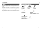
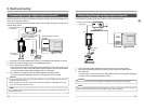
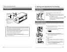
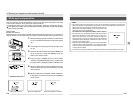
Fall prevention
Fall prevention
wire chain
2. Before shooting (continued)
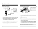
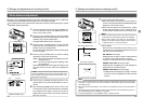
Mounting screw dimen-
sions:
• When mounted on top:
10 mm
• When mounted on un-
derside: 6 mm
MEMO
• Special attention is required when mounting the unit to the wall or ceiling. Rather
than attempting to do it yourself, request a qualified person to perform such instal-
lation. Falling of the unit may result in bodily injury.
• To prevent the unit from falling, connect the unit to a strong surface with a wire
chain, etc. When connecting such chain, use the bracket locking screw hole on the
side which the camera mounting bracket is not mounted.
• When mounted on top: M 2.6 × 10 mm (provided)
• When mounted on underside: M 2.6 × 6 mm
Take special caution to the length of the optional wire as well.
• For the fall-preventive wire, use the one with the strength that is more than 10 times
of a mass including the lens.
E21
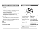
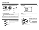
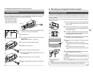
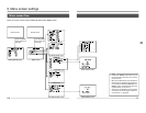
Lens settings
3. Settings and adjustments for shooting
Set according to whether the used lens to be used is an auto-iris lens or a manual lens.
Set the [IRIS MODE] on the [EXPOSURE] screen.
(੬ page E33)
AUTO :Setting when auto-iris lens is used in auto mode.
MANUAL: Set when using a manual lens, using an auto-iris
lens in MANUAL or no lens.
* If the auto-iris lens cable is not connected to
the [LENS] connector, the setting automatically
becomes “MANUAL”.
(Default setting: AUTO)
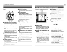
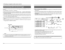
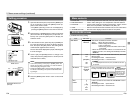
Monitor adjustment
ON
OFF
1234
The colour contrast and brightness are adjusted whilst, built-in test signals of the camera are
being displayed on the PC monitor.
1.
Connect the [ANALOG OUT] connector or the
[IEEE1394] connector to the PC.
2.
Set the function setting switch NO.1 on the switch panel
on the side of the KY-F1030 to “ON”.
3.
Turn ON the KY-F1030, and then start the PC.
* When connecting through the [IEEE1394] connector,
power is supplied from the PC.
4.
Adjust the monitor.
MEMO
• For how to adjust, see the instructions for the employed
monitor.
• The peak level of the test signal is set to 0.7V from the fac-
tory. To use 0.57V, change the setting by [TEST PATTERN]
➝ [LEVEL] on the [SYSTEM SETTING] screen.
੬ page E40 TEST PATTERN
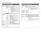
Set the used Lens
UP/AW
SET
MENU
DOWN
1234
ANALOG OUT
IEEE1394
LENS
MD
CONTROL
REMOTE
DC IN
POWER
SEE INSTRUCTION MANUAL
[ANALOG OUT] [IEEE1394]
Inside window
Default Setting Switch