


E8
Cautionary notes for the correct usage of this product
• Before recording an important event, etc., always check to make sure that this product is
working properly.
• We are not liable for any missed recordings caused by malfunction of this unit, etc.
Ⅵ Phenomena unique to CCD
• Smearing and blooming
When using CCD to shoot a bright light source, a smearing effect may occur running a
white line vertical to the light source. In addition, a blooming effect may also occur when the
light source is extremely bright, spreading light to the source surroundings.
• Line distortion
Line and patterns may appear distorted when shot.
• White spots
White spots may appear on the screen when operating under high temperatures. Always
use the product under recommended ambient temperatures.
White spots may also appear at a slow shutter speed setting (1/8 s or higher).
To reduce this phenomenon, this product is provided with at built-in white spot compensa-
tion function. ( Z page E28 White spot compensation)
Ⅵ Cautionary notes
• Influence of strong electric waves and magnets
Screen noise and discolouration may occur when using the product near antennas of ra-
dios and televisions or near transformers, monitors, etc. with strong magnetic force.
• Compatible lenses ( ੬ page E17 Mounting the lens)
Although the lens mount of this product is a type C mount, take caution as there are restric-
tions on the lenses that can be used.
• To save electricity, turn off the system when not in use.
Ⅵ Cleaning
When clean the equipment please use dry cleaning cloth or wet cleaning cloth with small
amount of alcohol.
Do not spill any liquid into KY-F1030.
Ⅵ Do not install the KY-F1030 in a location where it is subject to radiation or x-rays or
where corrosive gasses are generated.
1. Introduction (continued)
E9
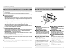
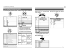
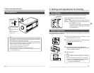
Part names and their functions
³ Lens mount
Although the lens mount conforms to the
type C mount lens.
Mounting the lens ( ੬ page E17)
· Camera mounting bracket
Although the mounting bracket is mounted
on the bottom of the camera when shipped,
the bracket can also be mounted on the
top of the camera.
Mounting the camera ( ੬ page E19)
» Locking screws for the camera
mounting bracket
(M2.6 × 6mm, 3 units)
CAUTION
● Always use the attached screws. Using
screws that exceed 6mm may result in mal-
function of the unit.
● When the bracket is mounted on the top sur-
face of the camera, use the provided screws
(length: 10 mm).
¿ Screw holes for mounting the
camera (1/4-inch)
Used when mounting the camera to a fixer
or rotating platform.
´ Side switch panel (inside)
Open the door to access a switch panel
used when making settings on menus.
Side switch panel section ( ੬ page E11)
² [FOCUS] backfocus adjustment
screw
This is adjusted to the optimal wide setting
when shipped from the factory. Should be
readjusted when required by the lens used
in combination with the camera.
Focus adjustment ( ੬ page E24)
¶ [LOCK] backfocus locking screw
Screw to lock the backfocus adjustment
mechanism.
Focus adjustment (੬ page E24)
[Front and bottom]
³
·
»
¿
´
²