


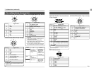

E10
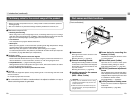
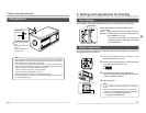
[Rear]
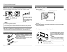
¸ [POWER] indicator
Lights when power is supplied to the cam-
era.
¹ [DC IN] connector
(Mini DIN 8-pin, female)
Power (DC 12V) for the camera is supplied
through this inlet.
For the power supply, use the AA-P700 AC
adapter.
Pin configurations of connectors ( ੬ page
E12)
Connecting power ( ੬ page E18)
Ƹ [REMOTE] terminal
(Metal 10-pin, female)
Used to connect external devices such as
a trigger switch or flash unit.
Pin configurations of connectors ( ੬ page
E12)
Connecting through digital output connec-
tor ( ੬ page E14)
Synchronizing flash and trigger ( ੬ page
E26)
ƹ [MD CONTROL] lens connector
2
To connect the lens control cable (for zoom,
focusing control).
Pin configurations of connectors ( ੬ page
E12)
Mounting the lens ( ੬ page E17)
ANALOG OUT
IEEE1394
LENS
MD
CONTROL
REMOTE
DC IN
POWER
SEE INSTRUCTION MANUAL
¹Ƹ
ƹµ
º¾
¸
1. Introduction (continued)
º [ANALOG OUTPUT] connector
Analog output connector for video signal.
Used when connecting the camera to an
SXGA-compliant capture board or the des-
ignated scan rate converter integrated with
the computer.
Pin configurations of connectors ( ੬ page
E13)
MEMO
Only output when the AC adapter (AA-
P700) is used as the power supply.
¾ [IEEE1394] digital output con-
nector
Digital output connector for video signal.
Used when connecting to the PC
’
s IEEE
1394 host adapter.
Pin configurations of connectors ( ੬ page
E13)
µ [LENS] connector 1
To connect the lens
’
camera cable (for iris
control, power supply).
Pin configurations of connectors ( ੬ page
E12)
Mounting the lens ( ੬ page E17)
MEMO
The motorized lens can only be controlled
(zoom, IRIS, focus) from the KY-F1030 when
the AC adapter (AA-P700) is used as the power
supply.
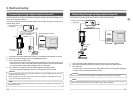
E11
Part names and their functions (continued)
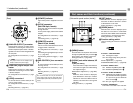
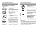
ƺ [MENU] button
Press this button to output the menu screen
through the [ANALOG OUT] connector ᕦ.
Press again to stop display of the menu.
Setting procedure ( ੬ page E32)
ƻ [UP/AW] auto white balance, UP
button
● [AW (auto white)]
Press this button to adjust the white bal-
ance when the light source illuminating
the subject changes.
White balance adjustment ( ੬ page E22)
● [UP]
While the menu screen is displayed,
press this button to move up to a select-
able item on the menu. While an item is
selected, use this button to change the
set value.
Setting procedure ( ੬ page E32)
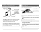
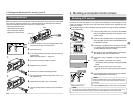
[Side switch panel section (inside)] Ƽ [SET] button
While the menu screen is displayed, press
this button to select a submenu or confirm
a selected item or set value.
Setting procedure( ੬ page E32)
ƽ [DOWN] button
While the menu screen is displayed, press
this button to move down to a selectable
item on the menu. While an item is selected,
use this button to change the set value.
Setting procedure( ੬ page E32)
ƾ Function setting switch
Used for setting the functions of the KY-
F1030.
● Switch 1 <TEST PATTERN>
ON: Test signal is output.
OFF: The image being shot by the cam-
era is output.
Monitor adjustment ( ੬ page E21)
SYSTEM SETTING screen ( ੬ page E40)
● Switch 2 <MENU LOCK>
ON: Disables the [MENU] button ƺ.
OFF: Enables the [MENU] button ƺ.
● Switch 3 <SYNC ON GREEN>
ON: Applies the sync signal to the green
(G) channel of the video signal that
is output through the ANALOG
OUT connector º.
OFF: The sync signal is not applied.
● Switch 4 <RESERVED>
This switch is not used. Leave it at OFF.
UP/AW
SET
MENU
DOWN
1234
ƺƻƼ
ƽ
ƾ
ON
OFF
1234