


E10
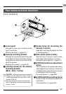
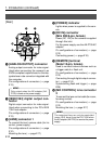
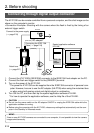
[Rear]
¸ [POWER] indicator
Lights when power is supplied to the cam-
era.
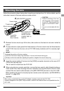
¹ [DC IN] connector
(Mini DIN 8-pin, female)
Power (DC 12V) for the camera is supplied
through this inlet.
For the power supply, use the AA-P700 AC
adapter.
Pin configurations of connectors ( ੬ page
E12)
Connecting power ( ੬ page E18)
Ƹ [REMOTE] terminal
(Metal 10-pin, female)
Used to connect external devices such as
a trigger switch or flash unit.
Pin configurations of connectors ( ੬ page
E12)
Connecting through digital output connec-
tor ( ੬ page E14)
Synchronizing flash and trigger ( ੬ page
E26)
ƹ [MD CONTROL] lens connector
2
To connect the lens control cable (for zoom,
focusing control).
Pin configurations of connectors ( ੬ page
E12)
Mounting the lens ( ੬ page E17)
ANALOG OUT
IEEE1394
LENS
MD
CONTROL
REMOTE
DC IN
POWER
SEE INSTRUCTION MANUAL
¹Ƹ
ƹµ
º¾
¸
1. Introduction (continued)
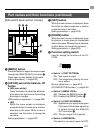
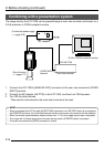
º [ANALOG OUTPUT] connector
Analog output connector for video signal.
Used when connecting the camera to an
SXGA-compliant capture board or the des-
ignated scan rate converter integrated with
the computer.
Pin configurations of connectors ( ੬ page
E13)
MEMO
Only output when the AC adapter (AA-
P700) is used as the power supply.
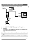
¾ [IEEE1394] digital output con-
nector
Digital output connector for video signal.
Used when connecting to the PC’s IEEE
1394 host adapter.
Pin configurations of connectors ( ੬ page
E13)
µ [LENS] connector 1
To connect the lens’ camera cable (for iris
control, power supply).
Pin configurations of connectors ( ੬ page
E12)
Mounting the lens ( ੬ page E17)
MEMO
The motorized lens can only be controlled
(zoom, IRIS, focus) from the KY-F1030 when
the AC adapter (AA-P700) is used as the power
supply.