


E12
1
4
3
6
7
8
5
2
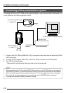
1. Introduction (continued)
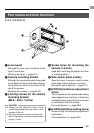
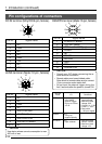
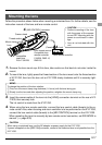
DC IN terminal (Mini DIN 8-pin, female)
Pin configurations of connectors
Pin no. Signal name
1NC
2 GND
3NC
4NC
5 GND
6 12V
7NC
8 12V
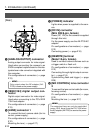
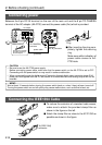
LENS terminal (Metal 12-pin, female)
Pin no. Signal name
1NC
2NC
3 GND
4NC
5 IRIS CONTROL
6 12V DC 400mA max.
7 IRIS POSITION
8 IRIS AUTO /MANU
9 to 12 NC
6
7
8
2
1
9
3
4
12
5
10
11
Terminal
name
2 TRG IN
3 WEN
4 FLASH
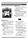
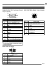
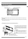
REMOTE terminal (Metal 10-pin, female)
Pin no. Signal name
1 A. WHITE L active
2 TRG IN L active
3
WEN L active 3.3V(p-p)
4 FLASH
5NC
6 RS-SDI
7 RS-SDO
8 GND
9 12V
10 OPERATION
1
2
8
7
10
6
3
4
5
9
CAUTION
• Consult your JVC dealer concerning the re-
mote terminal connection.
• Remote cable must use shielded cable.
Outer shield of remote cable must to connect
10-pin connector outer metal shell.
• Do not input the external trigger during the
first 5 seconds after the power is turned ON.
I/O
IN
• 3.3V CMOS
• Schmidt Trigger
• Pull-up to 3.3V at
4.7k Ω
OUT
• 3.3V (p-p)
negative polarity
OUT
• Open collector
Conditions
• Contact point
recommended
• Maximum rated
voltage: 5.3V
• H level: 2.4 ~ 5.0V
• L level: 0 ~ 0.5V
• Pulse width:
130 µs or higher
• Maximum rated
current: 150mA
• Maximum rated
voltage: 12V
CAUTION
Use device whose current consumption is max.
400 mA or less.