10
5 / BARS
∞/ AW
SETMENU
1234
9
ON
OFF
1234
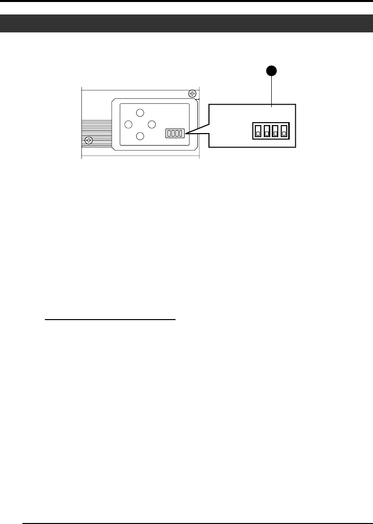
9 Function Setting Switch
Use for setting the functions of this unit.
Select the switches when the unit is at power
off condition.
● Switch 1 <DV OUTPUT>
[ON] : Compressed DV signal (IEEE1394)
of the camera images will be out-
put.
[OFF] : DV signal will not be output.
Note
If [ON] is selected, the analog output will
exhibit the same level of horizontal resolution
(about 540 lines) as the DV output.
● Switch 2 <DSUB OUTPUT>
[ON] : Y/C signal will be output.
[OFF] : RGB signal will be output.
Up:
Down:
● Switch 3 <SYNC ON GREEN>
[ON] : Sync signal will be superimposed
onto the Green (G) channel of the
video signal output to the [RGB, Y/
C, SYNC OUT] terminal
0
.
[OFF] : Sync signal will not be superim-
posed.
● Switch 4 <CONTROL MODE>
[ON] : Operate the camera via [DV] termi-
nal (IEEE1394).
Operation via [MENU], [SET], [5/
BARS], [∞/AW] buttons and the re-
mote control unit will not function.
[OFF] : Operate the camera via the buttons
on this unit or the remote control
unit. Operation via [DV] terminal
(IEEE1394) is not functional.
Part Names and Functions (continued)
1. Getting Started (continued)


